Starting clutch

a clutch and clutch technology, applied in the direction of fluid-actuated clutches, clutches, non-mechanical actuated clutches, etc., can solve the problems of increasing the amount, affecting the efficiency, and the supply of the pump capacity of the oil pump, so as to achieve sufficient cooling operation and efficiently cool down

Inactive Publication Date: 2008-06-19
NSK WARNER
View PDF28 Cites 31 Cited by
  • Summary
  • Abstract
  • Description
  • Claims
  • Application Information

AI Technical Summary

Benefits of technology

[0010]Accordingly, an object of the present invention is to provide a starting clutch in which heat of the clutch can be cooled efficiently with a small amount of lubricating oil and a sufficient cooling operation can be achieved even when an oil pump provided in an existing transmission is used.
[0012]According to the starting clutch of the present invention, the following effects can be obtained.
[0013]Since the piston for urging the substantially radial central portion of the friction plate to engage the friction plates with each other is provided, face pressure distribution on a friction surface of each friction plate becomes uniform, thereby providing a starting clutch having a good heat resisting ability and a stable operation.
[0014]Since the cooling oil supplied to the friction plates efficiently is temporarily trapped in an inner diameter side of a hub member and in the clutch thereby to absorb the heat from the clutch portion and then is quickly discharged from the clutch portion toward the transmission by a centrifugal action of the clutch portion, both reduction in the capacity of the oil pump and the heat resisting ability of the starting clutch can be compatible, thereby enhancing reduction in fuel consumption and enhancing reliability.

Problems solved by technology

On the other hand, the torque converter has disadvantages that a slip amount is increased during the torque transmission and that efficiency is relatively bad.
Thus, although an oil pump must has a great pump capacity, a pump capacity of an oil pump provided in the conventional transmission is insufficient, and, therefore, there arises a problem that such an insufficient oil pump cannot be mounted to the starting clutch as it is.
Further, since the conventional oil pumps perform the cooling operation with a small amount of oil, heat may be accumulated in the clutch portion and then the clutch may be burned.
In this case, however, since the lubricating oil is discharged faster from the clutch portion, heat exchange between the clutch portion and the oil cannot be achieved sufficiently, with the result that the cooling efficiency of the clutch may be worsened and the heat is apt to be accumulated in the clutch portion.

Method used


Image

  • Starting clutch
  • Starting clutch
  • Starting clutch

Examples


first embodiment

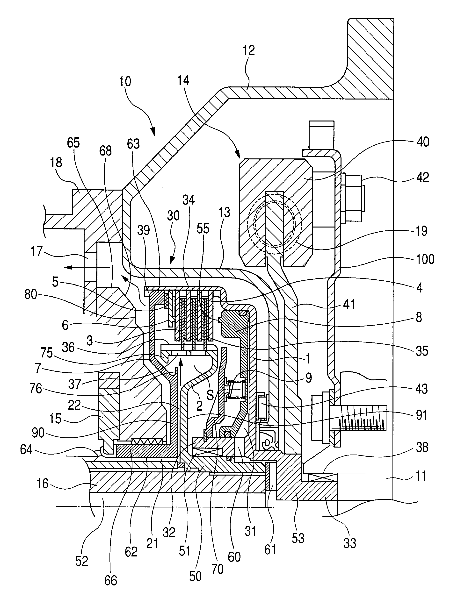
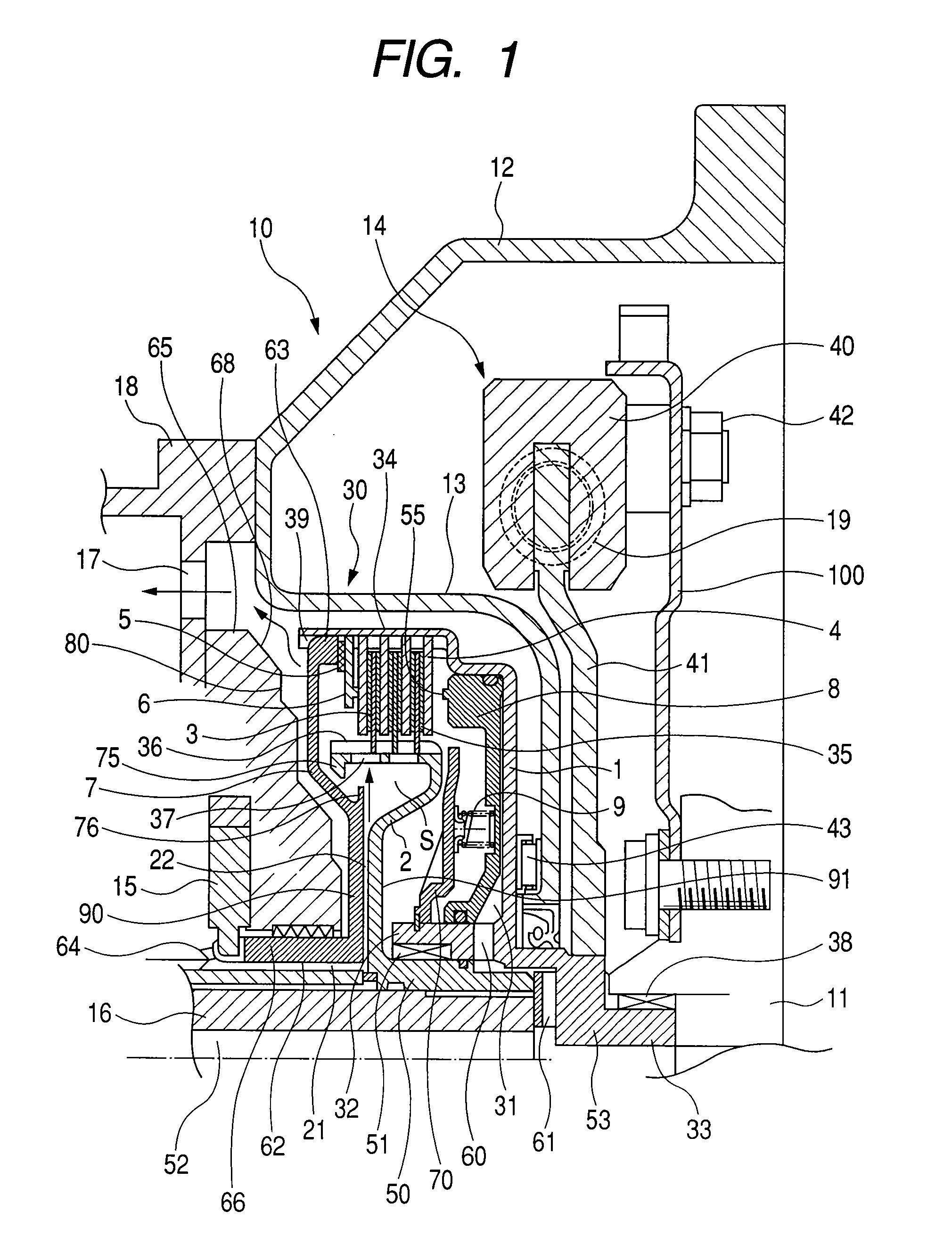
[0023]FIG. 1 is an axial sectional view showing a starting clutch according to a first embodiment of the present invention. The starting clutch 10 includes a clutch drum 1 and a wet type multi-plate clutch 30 housed within the clutch drum. The wet type multi-plate clutch 30 comprises substantially annular friction plates (internally-toothed plates) 3 as friction engaging elements at an output side and substantially annular separator plates (externally-toothed plates) 4 as friction engaging elements at an input side, which plates are arranged alternately along an axial direction within the clutch drum 1. Within one axial end (open end) of the clutch drum 1, a substantially annular backing plate 6 is fixedly supported by a substantially annular stop ring 5 in the axial direction, thereby holding the separator plates 4.

[0024]The annular clutch drum 1 is provided at its inner periphery with a central cylindrical portion 32 and is also provided at its outer periphery with an outer diamet...

second embodiment

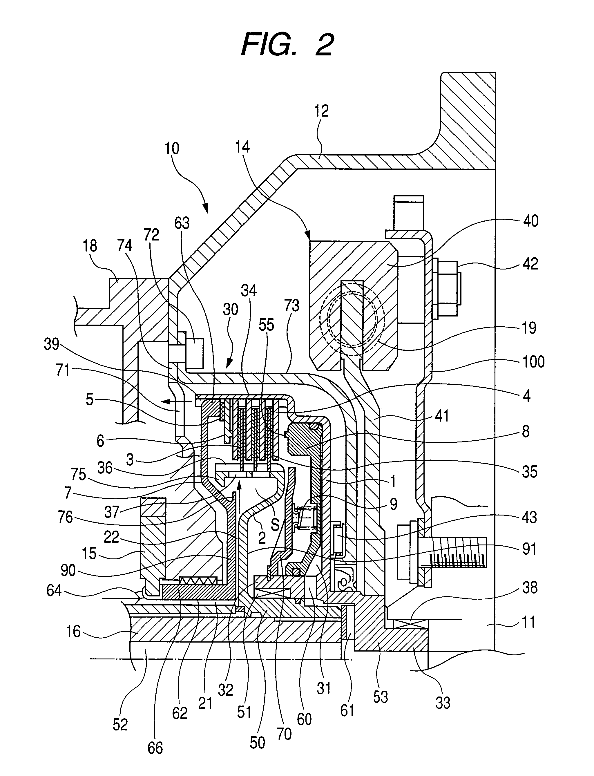
[0044]FIG. 2 is an axial sectional view showing a starting clutch according to a second embodiment of the present invention. Since a fundamental arrangement of the second embodiment is the same as that of the first embodiment, the detailed explanation thereof will be omitted.

[0045]The second embodiment differs from the first embodiment regarding a construction of a clutch cover and a lubricating oil discharging path. A clutch cover 73 covering the clutch portion 30 is provided independently from the housing 12. Although the connection to the clutch drum 1 is similar to that in the first embodiment, the clutch cover 73 is secured to a side wall of the housing 12 at the transmission side by bolts 72.

[0046]The side wall 74 is provided with a through hole 71 through which the lubricating oil which has lubricated the clutch portion 30 is discharged toward the transmission. The lubricating oil from the clutch portion 30 passes through the through hole 71 and flows toward the transmission....

third embodiment

[0050]FIG. 3 is an axial sectional view of a starting clutch according to a third embodiment of the present invention. The starting clutch 10 includes a clutch drum 1 and a wet type multi-plate clutch 30 housed in the clutch drum. The wet type multi-plate clutch 30 comprises substantially annular friction plates (internally-toothed plates) 3 as friction engaging elements at an output side and substantially annular separator plates (externally-toothed plates) 4 as friction engaging elements at an input side, which plates are arranged alternately along an axial direction within the clutch drum 1. Within one axial end (open end) of the clutch drum 1, a substantially annular backing plate 79 is fixedly supported by a substantially annular stop ring 5 in the axial direction, thereby holding the separator plates 4. The backing plate 79 is provided at it tip end with a curved portion 79a protruding toward the clutch portion.

[0051]The annular clutch drum 1 is provided at its inner periphery...


PUM


Abstract

The present invention provides a starting clutch disposed between a transmission and an engine and having a wet type multi-plate clutch for transmitting a power, in which the wet type multi-plate clutch includes a plurality of friction plates housed for an axial sliding movement, a clutch drum for housing the friction plates, and a piston for urging a radial central region or therearound of the friction plate to engage the friction plates, and oil which has lubricated the wet type multi-plate clutch is temporarily trapped within the clutch drum and then is discharged.

Description

BACKGROUND OF THE INVENTION[0001]1. Field of the Invention[0002]The present invention relates to a starting clutch which can be used in place of a torque converter for a motor vehicle and the like.[0003]2. Description of the Related Art[0004]In the past, in automatic transmissions, the starting of a vehicle has been achieved through torque transmission of a torque converter. The torque converter has been mounted on many vehicles since the torque converter serves to amplify the torque and also provides smooth torque transmission.[0005]On the other hand, the torque converter has disadvantages that a slip amount is increased during the torque transmission and that efficiency is relatively bad.[0006]Thus, in recent years, it has been proposed that a starting clutch is used in place of the torque converter and it has also been implemented that, in a low speed range, the torque is amplified by increasing a gear ratio and by increasing the number of transmission stages.[0007]In general, th...

Claims


Application Information

Patent Timeline
Patent Type & Authority Applications(United States)
IPC IPC(8): F16D13/52
CPCF16D25/0638F16D13/54F16D2069/004F16D25/123
Inventor MIYAZAKI, TOMOYUKIKITAHARA, SHUNSAWAYANAGI, MANABUSAKAI, MASAKIIKEDA, YOSUKE
Owner NSK WARNER
Why Eureka
Try Eureka