Supercharge Your Innovation With Domain-Expert AI Agents!

High Speed Latch Comparators

a high-speed latch and comparator technology, applied in pulse generators, pulse techniques, instruments, etc., can solve the problems of data conversion often presented as a bottleneck, impede the rate at which information is transmitted, delay processing,

Inactive Publication Date: 2008-06-19
AVAGO TECH INT SALES PTE LTD
View PDF36 Cites 2 Cited by
  • Summary
  • Abstract
  • Description
  • Claims
  • Application Information

AI Technical Summary

Benefits of technology

The present invention relates to high speed latch comparators and a latch circuit that includes a bistable pair and a vertical latch. The invention reduces the time required for the latch circuit to reach its steady state voltage, which is the time needed for the current signal to exceed the bias current. The invention also decreases the power consumed by the latch circuit during the reset phase. The technical effect of the invention is to improve the speed and efficiency of the latch circuit.

Problems solved by technology

In the design of network technologies, data conversion has often presented itself as a bottleneck that impedes the rate at which information is transmitted.
Bit errors can adversely effect the performance of a system that uses the digital output of ADC 200.
However, this solution delays processing, complicates circuit design, uses additional die area, and consumes more power.

Method used


Image

  • High Speed Latch Comparators
  • High Speed Latch Comparators
  • High Speed Latch Comparators

Examples


Embodiment Construction

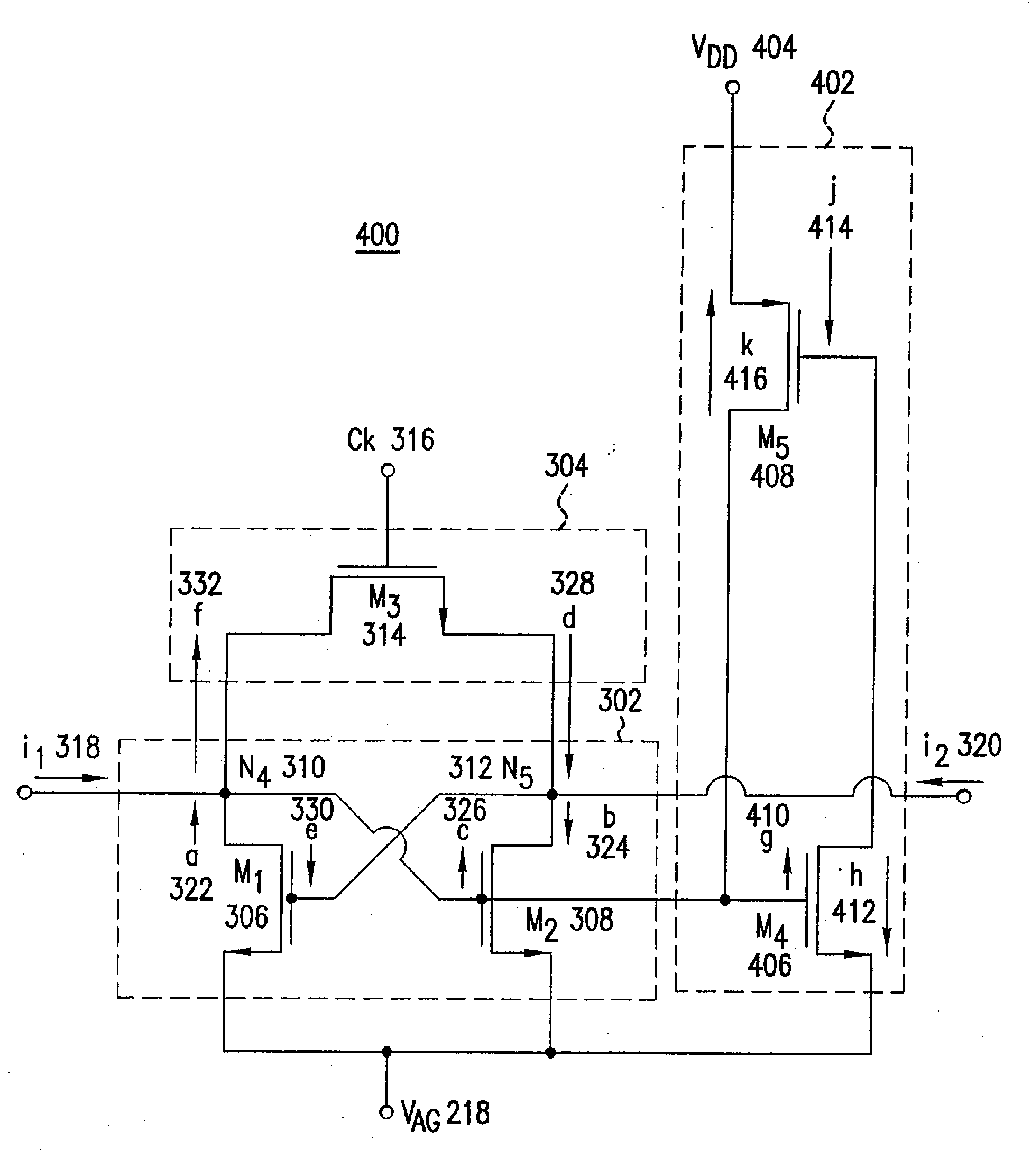
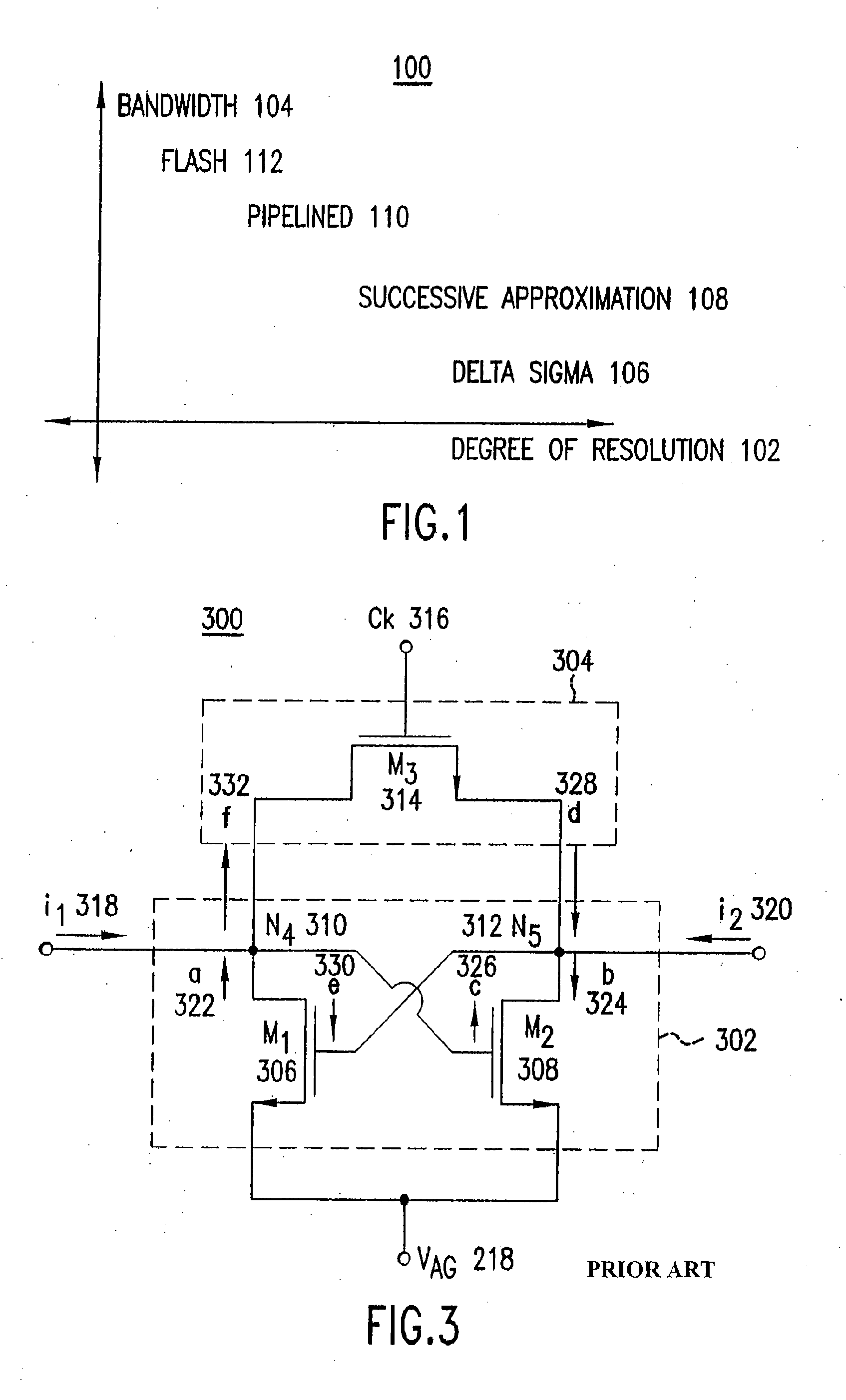
[0061]The present invention relates to high speed latch comparators. FIG. 4 is a schematic diagram of a latch circuit 400 that explains the present invention. Latch circuit 400 comprises bistable pair 302 connected between reset switch 304 and analog ground VAG 218. (Alternatively, analog ground VAG 218 can be replaced by first supply voltage VSS.) Preferably, bistable pair 302 comprises first NMOSFET M1 306 and second NMOSFET M2 308 connected in the same manner as in latch circuit 300. Ideally, M1 306 and M2 308 are matched transistors. Preferably, each of M1 306 and M2 308 has a gain greater than one. However, bistable pair 302 can function if the product of the individual gains of M1 306 and M2 308 (i.e., the loop gain) is greater than one. Preferably, reset switch 304 comprises third NMOSFET M3 314. Clock waveform Ck 316 is applied to the gate terminal of M3 314.

[0062]A vertical latch 402 is connected between analog ground VAG 218 and a second supply voltage “VDD”404. Preferably...


PUM


Abstract

In a latch circuit having a bistable pair of cross connected transistors of a first polarity and a third transistor of a second polarity, a current signal greater than a bias current is received at a latch circuit port, amplified with the third transistor, and applied to the latch circuit port. This decreases the time in which the latch circuit port receiving the current signal greater than the bias current reaches a steady state voltage.

Description

CROSS-REFERENCE TO RELATED APPLICATIONS[0001]This application is a divisional of U.S. application Ser. No. 10 / 649,808, filed Aug. 28, 2003, which is a continuation of U.S. application Ser. No. 10 / 083,463, filed Feb. 27, 2002, now U.S. Pat. No. 6,639,430, which claims the benefit of U.S. Provisional Application No. 60 / 271,425, filed Feb. 27, 2001, each of which is incorporated herein in its entirety by reference.BACKGROUND OF THE INVENTION[0002]1. Field of the Invention[0003]The present invention relates to high speed latch comparators.[0004]2. Background Art[0005]Commercialization of the Internet has proven to be a mainspring for incentives to improve network technologies. Development programs have pursued various approaches including strategies to leverage use of the existing Public Switched Telephone Network and plans to expand use of wireless technologies for networking applications. Both of these approaches (and others) entail the conversion of data between analog and digital fo...

Claims


Application Information

Patent Timeline
Patent Type & Authority Applications(United States)
IPC IPC(8): H03K3/45H03L7/00H03K3/012H03K3/356
CPCH03K3/012H03K3/356043H03K3/35613H03M1/362H03K3/356191H03M1/002H03K3/356182
Inventor BULT, KLASSVAN DER PLASSCHE, RUDYMULDER, JAN
Owner AVAGO TECH INT SALES PTE LTD
Features
  • R&D
  • Intellectual Property
  • Life Sciences
  • Materials
  • Tech Scout
  • Unparalleled Data Quality
  • Higher Quality Content
  • 60% Fewer Hallucinations
Learn More