

Multiscreen display apparatus
a multi-screen display and display device technology, applied in the direction of electric digital data processing, instruments, computing, etc., can solve the problems of circuit scale, complicated configuration, limited number of daisy-chained image display units, etc., and achieve the effect of high quality
- Summary
- Abstract
- Description
- Claims
- Application Information
AI Technical Summary
Benefits of technology
Problems solved by technology
Method used
Image

Examples
first embodiment
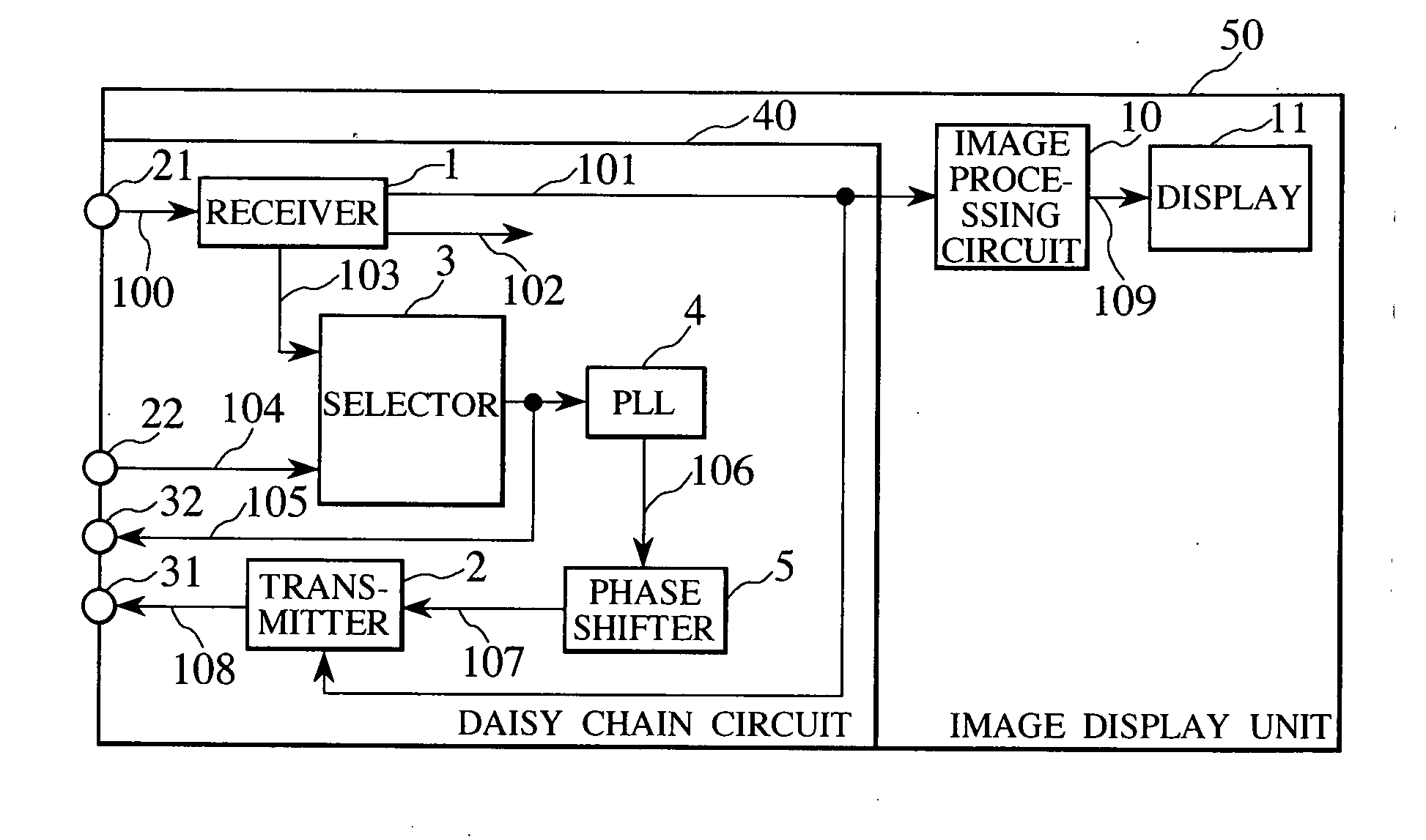
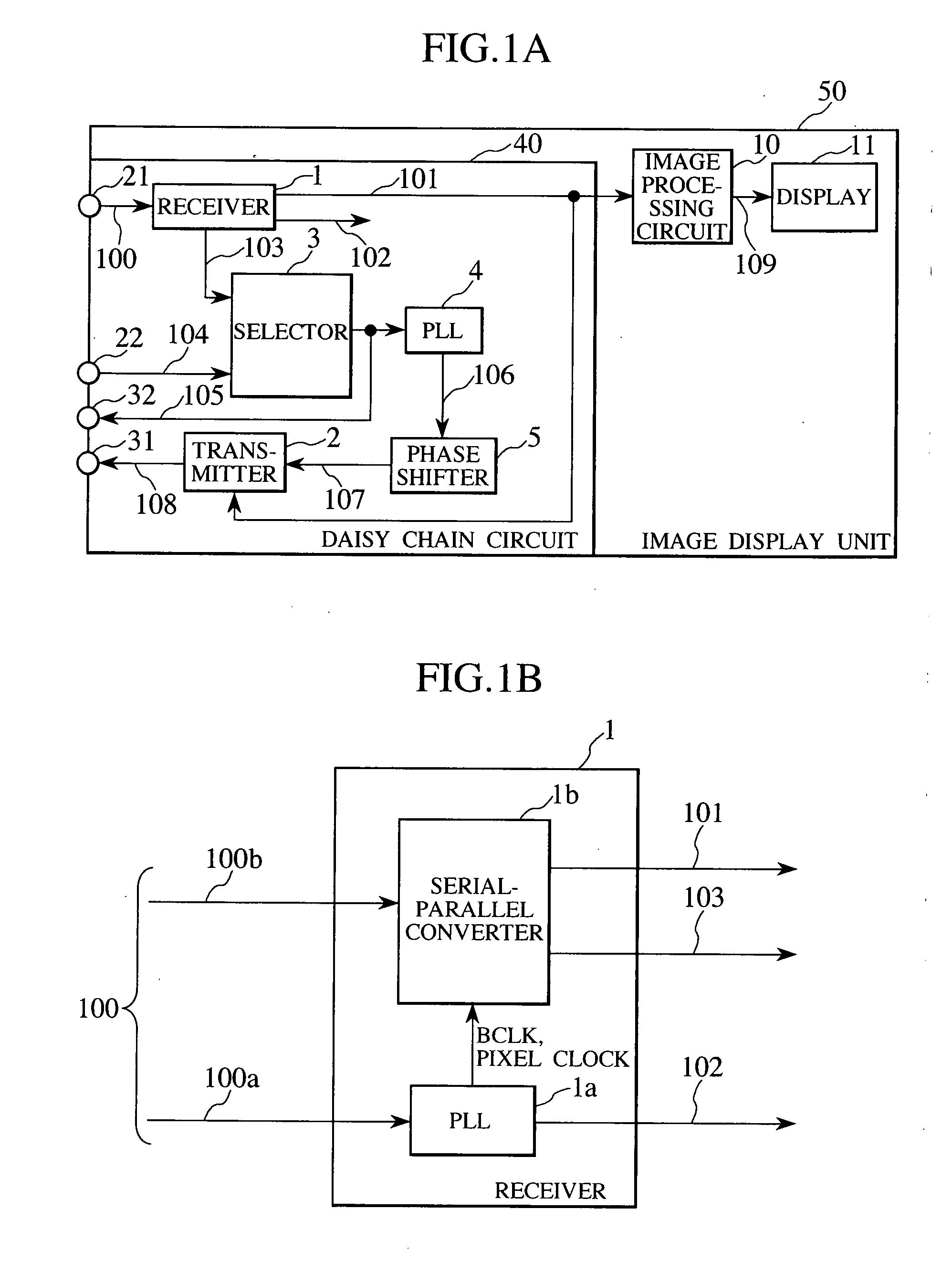
[0028]FIG. 1A is a schematic block diagram of an image display unit which is a component of a multiscreen display apparatus and indicates the present invention. As well, FIG. 1B is a schematic block diagram of a receiver included in a daisy chain circuit in the image display unit.
[0029]In FIG. 1A, the image display unit 50 in the multiscreen display apparatus has an end provided with: an image signal input terminal 21 to which a TMDS serial high speed signaling format digital image signal 100 is input; a reference signal input terminal 22 to which a reference signal (hereinafter denoted as “reference input signal”) 104 is input from the outside; an image signal output terminal 31 which outputs a serial high speed signaling format digital image signal 108; and a reference signal output terminal 32 which outputs a reference signal (hereinafter denoted as “reference output signal”) 105 to the outside.
[0030]Note that if the high speed digital image signal 100 employs the TMDS signaling ...
second embodiment
[0060]FIG. 4 is a schematic block diagram of the configuration of each of image display units constituting a multiscreen display apparatus according to the present invention.
[0061]The second embodiment is different from the first embodiment in that the phase shifter to correct the phase of the pixel clock 106 generated by the PLL 4 is inserted between the reference signal 22 and the selector 3.
[0062]As shown in FIG. 4, an image display unit 50A in the second embodiment includes a daisy chain circuit 40A, an image processing circuit 10 and a display 11.
[0063]The daisy chain circuit 40A includes a receiver 1, a transmitter 2, a phase shifter 5A, a selector 3 and a PLL 4.
[0064]The receiver 1 receives the serial high speed digital image signal 100 entered from the image signal input terminal 21. In the high speed digital image signal 100, the pixel clock 100a is included. Based on the pixel clock 100a, the receiver 1 uses the internal PLL 1a to generate a bit clock (BCLK) needed for ser...
third embodiment
[0082]FIG. 8 is a schematic block diagram of the configuration of each of image display units constituting a multiscreen display apparatus according to the present invention.
[0083]The third embodiment is different from the first embodiment in that the pixel clock 102 or the external pixel clock entered externally as the reference input signal is selected by the selector 6 and the output pixel clock is obtained by correcting the phase or delay of the selected pixel clock. Therefore, no PLL is used to generate the output pixel clock. In other terms, the present embodiment is identical to the first embodiment. Each element having the same function as the corresponding one is given the same reference numeral and its redundant description thereof is omitted.
[0084]The daisy chain circuit 40B in the image display unit 50B of the present embodiment includes a receiver 1, a transmitter 2, a selector 6 and a phase shifter 5.
[0085]The receiver 1 receives the serial high speed digital image sig...
PUM
 Abstract
Description
Claims
Application Information