Drive Method of Moving Body, Stage Unit, and Exposure Apparatus

a technology of moving bodies and stage units, applied in the direction of process and machine control, printing, instruments, etc., can solve the problems of increasing reducing the exposure accuracy, and reducing the size of the exposure apparatus, so as to prevent an unbalanced load, shorten the stroke distance of the counter mass, and reduce the effect of unbalanced load

Active Publication Date: 2008-06-19
NIKON CORP
View PDF40 Cites 61 Cited by
  • Summary
  • Abstract
  • Description
  • Claims
  • Application Information

AI Technical Summary

Benefits of technology

[0014]With this method, because an initial velocity in the first direction is given to the second moving body when the first moving body moves in the first direction, in the case the system including the first moving body and the second moving body follows the law of conservation of momentum, when the first moving body moves in the first direction, the second moving body moves in the direction opposite to the first direction receiving the reaction force of the drive force. However, at this point, a movement in the first direction due to the initial velocity is also performed, therefore, as a consequence, the second moving body moves in the direction opposite to the first direction only by a distance of the movement distance in the first direction caused by the initial velocity subtracted from the movement distance of the second moving body during free motion according to the law of conservation of momentum due to the reaction force of the drive force that drives the first moving body in the first direction, and the movement distance of the second moving body becomes shorter. Especially, in the case the first moving body moves in the first direction accompanied by acceleration and deceleration, because the second moving body moves in the first direction during the deceleration of the first moving body, the moving distance in the opposite direction of the first direction of the second body that has received the reaction force of the drive force of the first moving body in the first direction can be further reduced. Accordingly, with the first drive method of the present invention, the strokes necessary for movement of the second body can be shortened without necessarily increasing the size of the second moving body. Especially in the case the first moving body performs an operation that includes stepping movement in the first direction, because the first moving body alternately repeats acceleration and deceleration in the first direction, the strokes in the first axis direction (the first direction and the direction opposite to the first direction) necessary for movement of the second moving body can be made the shortest.
[0016]With this method, because position setting of the second moving body is to be performed offset in the first direction when the first moving body moves in the first direction, in the case the first moving body and the second moving body follow the law of conservation of momentum, when the first moving body moves in the first direction, the second moving body moves in the direction opposite to the first direction receiving the reaction force of the drive force. However, the moving distance of the second moving body is canceled out by the offset amount, which makes the moving distance of the second moving body shorter by the off set amount. Accordingly, with the second drive method of the present invention, the strokes necessary for movement of the second moving body can be made shorter, without necessarily increasing the size of the second moving body.
[0019]With this stage unit, because the control unit gives an initial velocity in the first direction to the counter mass when the stage moves in the first direction, when the stage moves in the first direction driven by the first drive unit, the counter mass moves in the direction opposite to the first direction receiving the reaction force of the drive force according to the law of conservation of momentum. However, at this point, a movement in the first direction due to the initial velocity is also performed, therefore, as a consequence, the counter mass moves in the direction opposite to the first direction only by a distance of the movement distance in the first direction caused by the initial velocity subtracted from the movement distance of the counter mass during free motion according to the law of conservation of momentum due to the reaction force of the drive force that drives the stage in the first direction, and the movement distance of the counter mass becomes shorter. Especially, in the case the stage moves in the first direction accompanied by acceleration and deceleration, because the counter mass moves in the first direction during the deceleration of the stage, the moving distance in the opposite direction of the first direction of the counter mass that has received the reaction force of the drive force of the stage in the first direction can be further reduced. Accordingly, with the first stage unit of the present invention, the strokes necessary for movement of the counter mass can be shortened without necessarily increasing the size of the counter mass. Especially in the case the stage performs an operation that includes stepping movement in the first direction, because the stage alternately repeats acceleration and deceleration in the first direction, the strokes in the first axis direction (the first direction and the direction opposite to the first direction) necessary for movement of the counter mass can be made the shortest.
[0021]With this unit, because the control unit performs position setting of the counter mass offset in the first direction when the stage moves in the first direction, in the case the stage and the counter mass follow the law of conservation of momentum, when the stage moves in the first direction, the counter mass moves in the direction opposite to the first direction receiving the reaction force of the drive force. However, the moving distance of the counter mass is canceled out by the offset amount, which makes the moving distance of the counter mass in the direction opposite to the first direction shorter by the off set amount, which allows the strokes of the counter mass to be set short.
[0023]With this apparatus, because one of the first and second stage units of the present invention that can shorten the strokes necessary for movement of the counter mass without necessarily increasing the size of the counter mass is used as the drive unit of the object, the size of the entire apparatus can be reduced by the smaller stage unit and the influence of vibration due to the reaction force during the drive of the stage can almost be removed, which makes it possible improve the transfer accuracy (exposure accuracy) of the pattern by the improvement in position controllability of the stage, or consequently, the position controllability of the object.

Problems solved by technology

However, from the level required in fine processing, the reaction force released at the datum gave vibration to the projection optical system or to the stage to no small extent, and especially in the scanning stepper that performs scanning exposure while scanning the stage (or consequently, the wafer or the reticle), the vibration caused by the reaction force was a factor that caused a decrease in the exposure accuracy.
Further, transmission of the reaction force can be prevented almost completely in the case when the reaction force is absorbed using the counter mass mechanism; however, in the conventional counter mass mechanism, because a counter mass was used that moves in a direction opposite to the drive direction of the stage by a distance proportional to the driving distance of the stage, strokes corresponding to all the strokes of the stage had to be prepared also for the counter mass, which led to an increase in the size of the exposure apparatus.
Accordingly, in the current situation, it is not necessarily the case that the size of the apparatus is small enough to satisfy a sufficient level.

Method used


Image

  • Drive Method of Moving Body, Stage Unit, and Exposure Apparatus
  • Drive Method of Moving Body, Stage Unit, and Exposure Apparatus
  • Drive Method of Moving Body, Stage Unit, and Exposure Apparatus

Examples


Embodiment Construction

[0041]An embodiment of the present invention will be described, referring to FIGS. 1 to 9B.

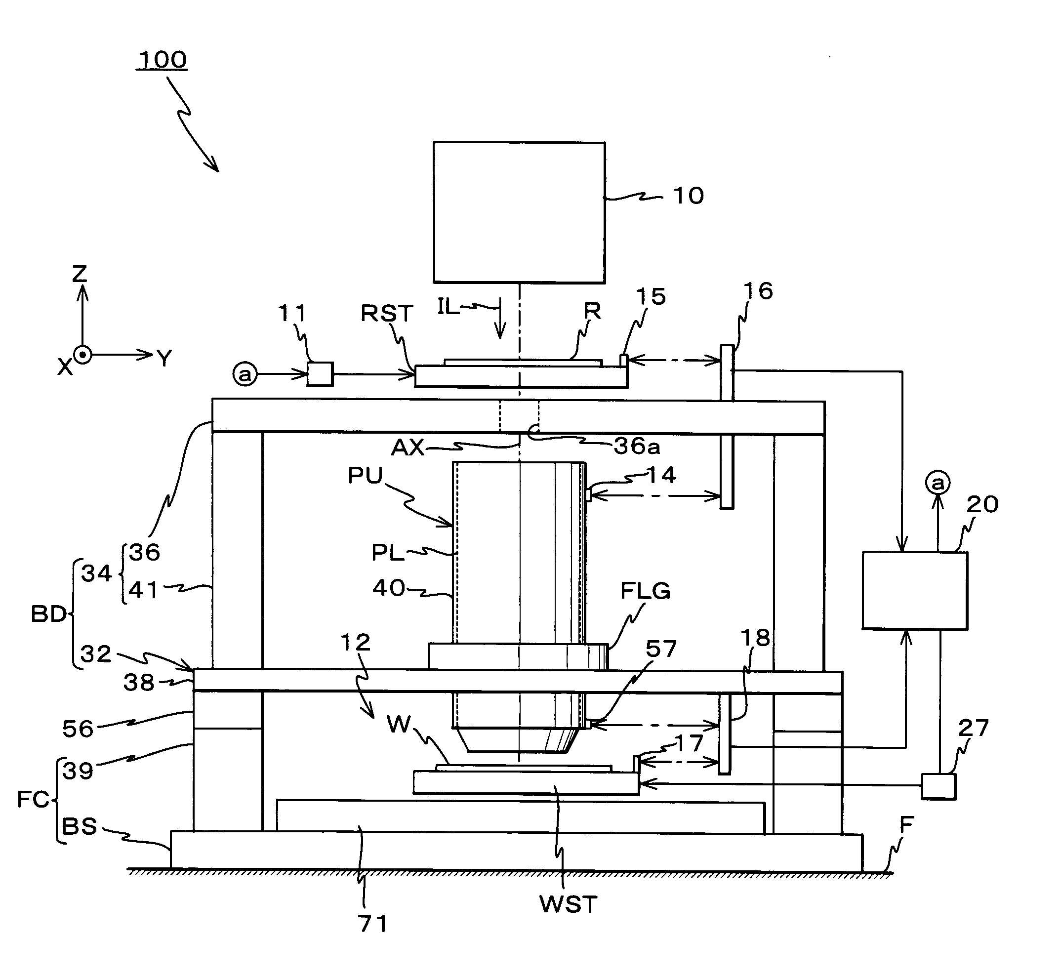
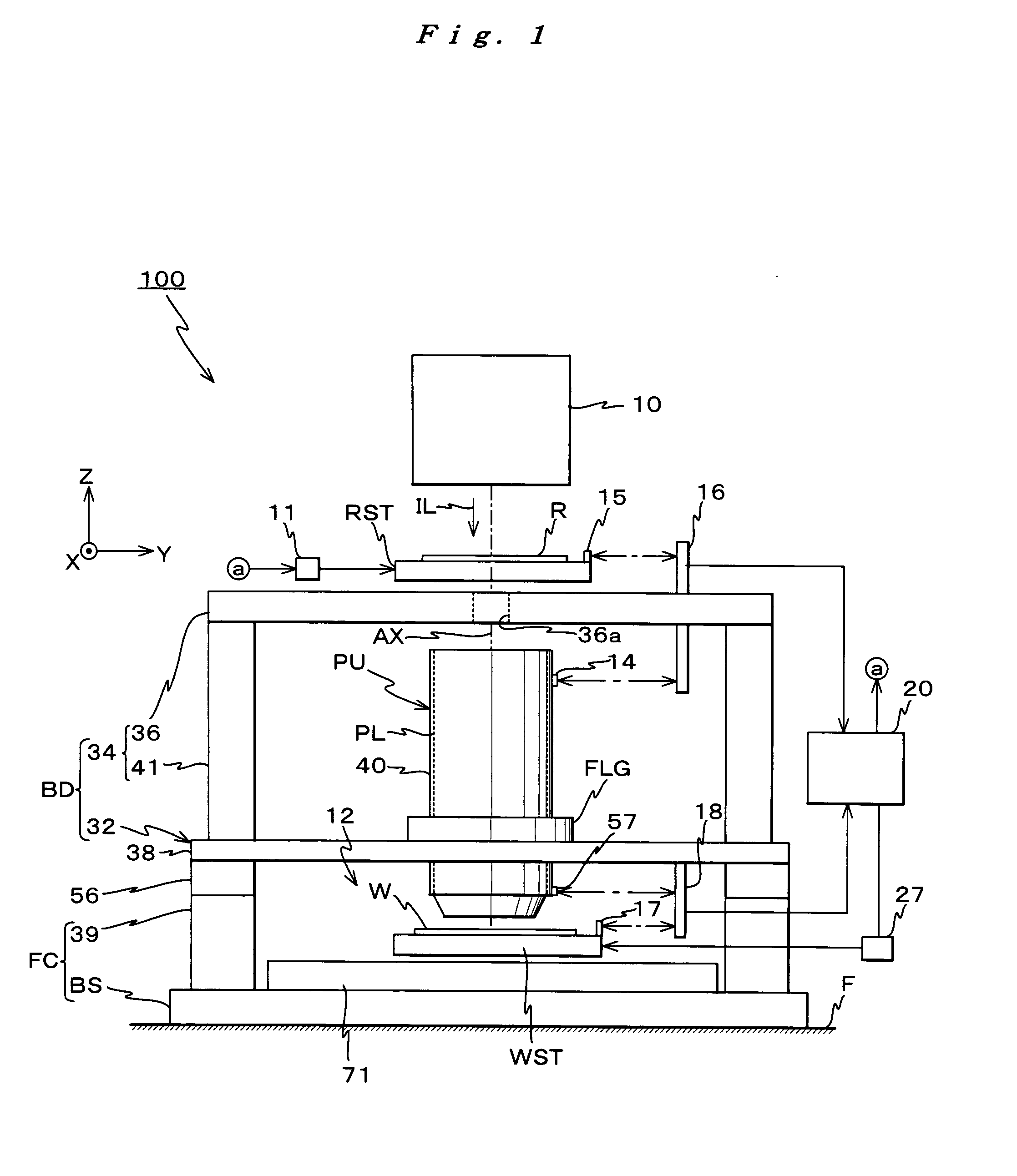
[0042]FIG. 1 shows the entire configuration of an exposure apparatus 100 related to the embodiment. Exposure apparatus 100 is a scanning exposure apparatus by a step-and-scan method, that is, the so-called scanning stepper. As it will be described later in the embodiment, a projection optical system PL is arranged, and in the description below, an optical axis direction AX of projection optical system PL will be described as the Z-axis direction, a direction within a plane orthogonal to the Z-axis direction in which a reticle R serving as a mask and a wafer W serving as an object are relatively scanned will be described as the Y-axis direction, and a direction orthogonal to both the Z-axis and the Y-axis will be described as the X-axis direction.

[0043]Exposure apparatus 100 is equipped with an illumination system 10 including a light source and an illumination optical system that illuminate re...


PUM

PropertyMeasurementUnit
wavelengthaaaaaaaaaa

Abstract

An exposure apparatus that comprises a stage (28) that moves in the X-axis direction, an X-axis linear motor (80) that drives the stage, a counter mass (30) that moves in a direction opposite to the stage due to the action of the reaction force of the drive force of the stage in the X-axis direction by the motor (80), X-axis trim motors (26A, 26B) that drives the counter mass in the X-axis direction, and a control unit that controls the trim motors and gives the counter mass an initial velocity in the +X direction when the stage is moved via the motor (80), for example, in the +X direction. Accordingly, the strokes required for the movement of the counter mass can be shortened without increasing the size of the counter mass.

Description

TECHNICAL FIELD[0001]The present invention relates to driving methods of moving bodies, stage units, and exposure apparatus, and more particularly to a drive method in which a first moving body and a second moving body that moves in a direction opposite to the first moving body by the reaction force of the drive force of the first moving body are driven, a stage unit to which the drive method is applied, and an exposure apparatus that is equipped with the stage unit.BACKGROUND ART[0002]Conventionally, in a lithography process for manufacturing a semiconductor device, a liquid crystal display device or the like, exposure apparatus such as a reduction projection exposure apparatus by a step-and-repeat method (the so-called stepper) or a scanning projection exposure apparatus by a step-and-scan method (the so-called scanning stepper (also called a scanner)) are relatively frequently used.[0003]With these types of exposure apparatus, in order to transfer a pattern of a reticle serving a...

Claims


Application Information

Patent Timeline
Patent Type & Authority Applications(United States)
IPC IPC(8): G03B27/58H02K41/00G03F7/20H01L21/027
CPCG03F7/70725G03F7/70766H01L21/68764H01L21/682H01L21/68714H01L21/68G03F7/70758
Inventor SHIBAZAKI, YUICHI
Owner NIKON CORP
Why Eureka
Try Eureka