
Frequency multiplexed, multiple channel heterodyne interferometer

a heterodyne interferometer and frequency multiplexing technology, applied in the field of heterodyne interferometers, can solve the problems of limiting the usefulness of high-bandwidth systems, slow acquisition and processing times, and distortion of signals transmitted between satellites and ground stations

Active Publication Date: 2008-06-19
THE BOEING CO
View PDF3 Cites 14 Cited by
  • Summary
  • Abstract
  • Description
  • Claims
  • Application Information

AI Technical Summary

Problems solved by technology

For example, a signal transmitted between a satellite and a ground station may undergo distortion as consequence of being transmitted through the atmosphere.
However, such non-heterodyne techniques typically have relatively slow acquisition and processing times which limit their usefulness in high bandwidth systems.
This intensive processing can also increase the necessary processing time for such techniques.
However, homodyne interferometers suffer from non-linearity effects at large vibration amplitudes, low signal-to-noise ratio caused by laser intensity fluctuations, and inverse frequency (i.e., 1 / f) detector noise.
Scanning interferometers use a single detector and electronic signal processor, but cannot simultaneously acquire vibration data from all locations on a device under test

Method used


Image

  • Frequency multiplexed, multiple channel heterodyne interferometer
  • Frequency multiplexed, multiple channel heterodyne interferometer
  • Frequency multiplexed, multiple channel heterodyne interferometer

Examples


Embodiment Construction

1. Overview

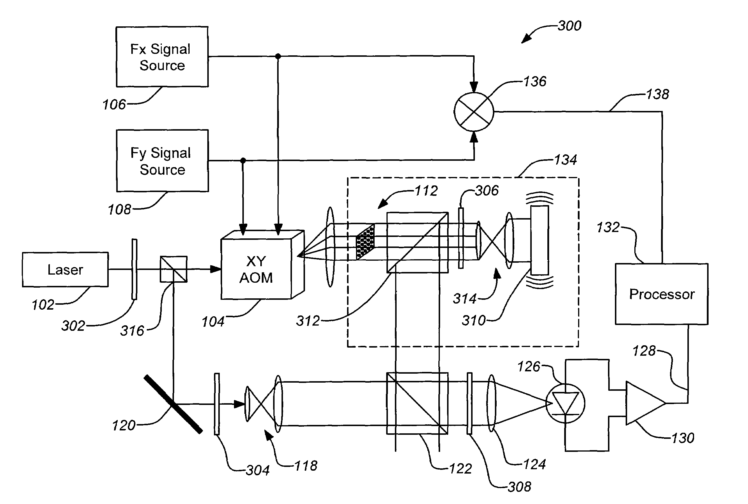
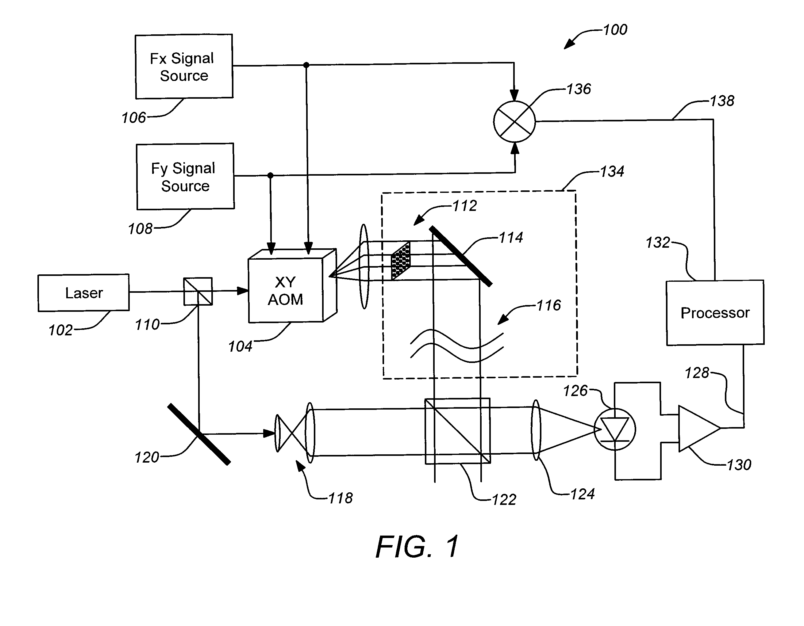
[0025]Various embodiments of the present invention employ the frequency shifting and beam steering properties of an AOM to perform both functions simultaneously. Also, the unique heterodyne frequency of each object beams allows a single detector to be used to detect multiple discrete heterodyne frequencies. Frequency multiplexing of multiple subaperture carriers onto one wide bandwidth channel requires signal processors to demultiplex each channel for subsequent OPD calculation. Recent advances in the size and processing power of FPGA and DSP chips makes this more economical. The added complication of the signal processing is offset by the simplicity and flexibility of the optics, modulators and detectors.

[0026]A heterodyne interferometer may be used for directly measuring the optical path difference between a test signal and a reference signal originating from a common beam of a laser. For example, the diameter of the beam is chosen so that wavefront tilt will be less th...


PUM


Abstract

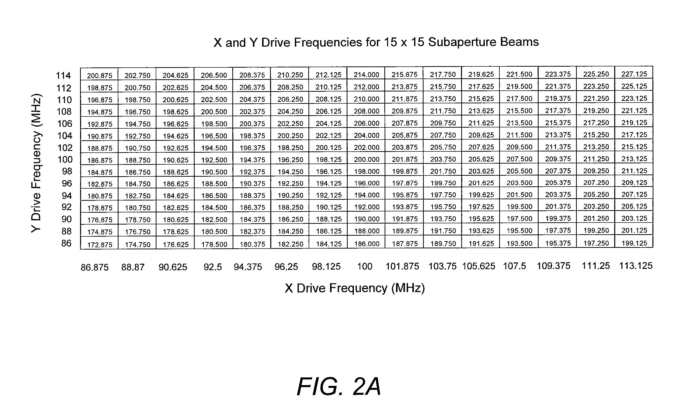
A novel technique using an acousto-optic modulator (AOM) as part of a heterodyne interferometer which measures optical path differences between a test signal and a reference signal is disclosed. An array of distinct frequencies are used to drive the AOM, yielding a spatially dispersed array of frequency-shifted subaperture beams of the test signal which are interfered with the wavefront to be measured and then combined with the dispersed reference signal. The frequency shifting of the AOM allows a single detector to collect the beams for signal processing to determine a measurement of the wavefront.

Description

BACKGROUND OF THE INVENTION[0001]1. Field of the Invention[0002]This invention relates to heterodyne interferometers. Particularly, this invention relates to heterodyne interferometers and their application to measuring wavefronts, such as in characterizing the optical aberrations of adaptive deformable mirrors or the wavefront piston induced by a vibrating mirror.[0003]2. Description of the Related Art[0004]In optical wireless communications there is a need to measure the distortions which may affect transmitted communication signals. For example, a signal transmitted between a satellite and a ground station may undergo distortion as consequence of being transmitted through the atmosphere. Measurements of a signal wavefront, such as an optical signal transmitted through the atmosphere, may be used to factor out the distortions that may occur in the transmission of a communications signal. Great pointing precision and overall communication efficiency can be achieved with more accura...

Claims


Application Information

Patent Timeline
Patent Type & Authority Applications(United States)
IPC IPC(8): G01B9/02
CPCG01H9/00G01B9/02003G01B9/02045
Inventor MUENTER, STEVEN E.
Owner THE BOEING CO
Learn More