Timing synchronization circuit with loop counter

Active Publication Date: 2008-06-19
MICRON TECH INC
View PDF8 Cites 39 Cited by
  • Summary
  • Abstract
  • Description
  • Claims
  • Application Information

AI Technical Summary

Problems solved by technology

The improved performance of computing integrated circuits and the growing trend to include several computing devices on the same board present a challenge with respect to synchronizing the time frames of all the components.
While the operation of all components in the system should be highly synchronized, i.e., the maximum skew in time between significant edges of the internally generated clocks of all the components should be minimized, it is not enough to feed the external clock of the system

Method used


Image

  • Timing synchronization circuit with loop counter
  • Timing synchronization circuit with loop counter
  • Timing synchronization circuit with loop counter

Examples


Embodiment Construction

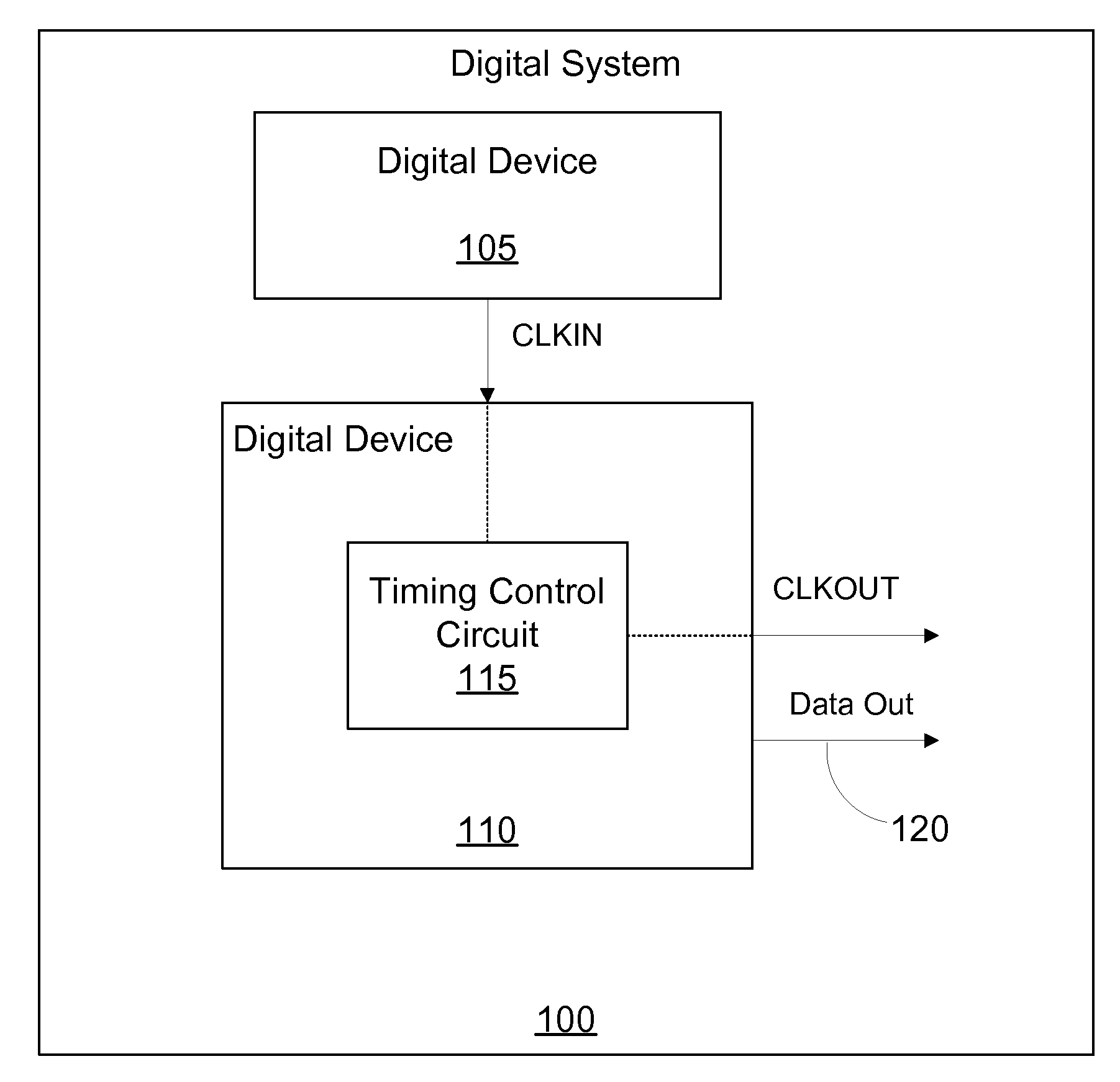
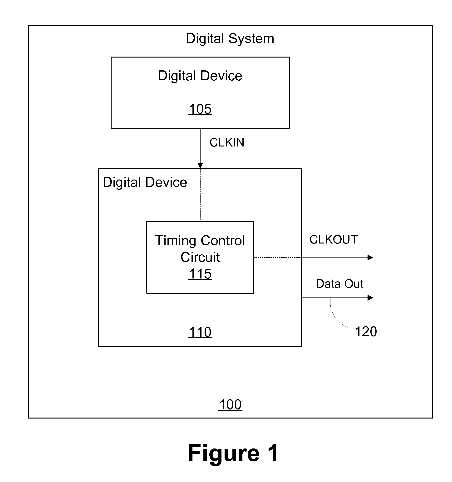
[0010]One or more specific embodiments of the present invention are described below. It is specifically intended that the present invention not be limited to the embodiments and illustrations contained herein, but include modified forms of those embodiments including portions of the embodiments and combinations of elements of different embodiments as come within the scope of the following claims.

[0011]Embodiments of the present invention will now be described with reference to the attached figures. Various structures, systems and devices are schematically depicted in the drawings for purposes of explanation only and so as to not obscure the embodiments of the present invention with details that are well known to those skilled in the art. Nevertheless, the attached drawings are included to describe and explain illustrative examples of embodiments of the present invention. The words and phrases used herein should be understood and interpreted to have a meaning consistent with the unde...


PUM


Abstract

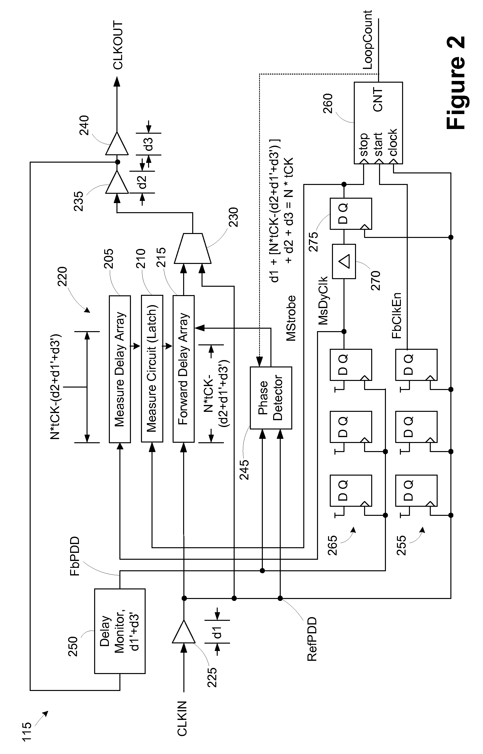
An apparatus for synchronizing an output clock signal with an input clock signal includes a first timing synchronization circuit, control logic, and a counter. The first timing synchronization circuit is operable to generate a delay to synchronize a reference clock signal representative of the input clock signal with a feedback clock signal representative of the output clock signal responsive a strobe signal. The control logic is operable to generate an enable signal based on the reference clock signal and generate the strobe signal based on the feedback clock signal. The counter is operable to count cycles of the reference clock signal occurring between the enable signal and the strobe signal to generate a loop count for the first timing synchronization circuit.

Description

BACKGROUND OF THE INVENTION[0001]The present invention relates generally to the field of timing synchronization and, more particularly, to a timing synchronization circuit with loop counter.[0002]Many high speed electronic systems operate with critical timing requirements that dictate a need to generate a periodic clock waveform possessing a precise timing relationship with respect to some reference signal. The improved performance of computing integrated circuits and the growing trend to include several computing devices on the same board present a challenge with respect to synchronizing the time frames of all the components.[0003]While the operation of all components in the system should be highly synchronized, i.e., the maximum skew in time between significant edges of the internally generated clocks of all the components should be minimized, it is not enough to feed the external clock of the system to all the components. This is because different chips may have different manufac...

Claims


Application Information

Patent Timeline
IPC IPC(8): H03L7/06H03L7/00G11C8/18
CPCG11C7/22G11C7/222H03L7/0812G06F11/1679G06F1/10G06F1/12G06F1/04H03L7/0814H03L7/0816
Inventor KWAK, JONGTAE
Owner MICRON TECH INC
Why Eureka
Try Eureka