Optical measurement instrument for living body

a technology of optical measurement and living body, applied in the field of optical measurement technology, can solve the problems that conventional techniques have not been able to remove noise signals, and achieve the effect of difficult separation and removal and few noise components

Active Publication Date: 2008-06-19
HITACHI LTD
View PDF8 Cites 40 Cited by
  • Summary
  • Abstract
  • Description
  • Claims
  • Application Information

AI Technical Summary

Benefits of technology

[0015]A plurality of factors can be detected from optical signals measured through the use of a plurality of light sources. For example, lights of 690 nm and 830 nm can be used to detect oxygenated hemoglobin and deoxygenated hemoglobin (Non-Patent Document 2). The separation calculation unit calculates a plurality independent components (separation signals), and mixing coefficient matrices that indicate how each of the independent components contributes to a plurality of measurement signals by means of, for example, an independent component analysis method (Non-Patent Document 3). The independent component analysis method can recover original measurement signals from the independent components and mixture coefficient matrices.
[0018]The present invention allows the noise components, such as the body motion noises that are difficult to be separated and removed, to be separated and removed, and provides signals with few noise components.

Problems solved by technology

However, when the noise signals show a similar variation as the target biological signals, conventional techniques have not been capable of removing the noise signals.
When a subject being tested is given a certain task in order to obtain a desired biological signal, for example, when the subject being tested is asked to play a simple voluntary movement at a given time, a displacement in an area being tested caused by the voluntary movement could lead to the noise.

Method used


Image

  • Optical measurement instrument for living body
  • Optical measurement instrument for living body
  • Optical measurement instrument for living body

Examples


Embodiment Construction

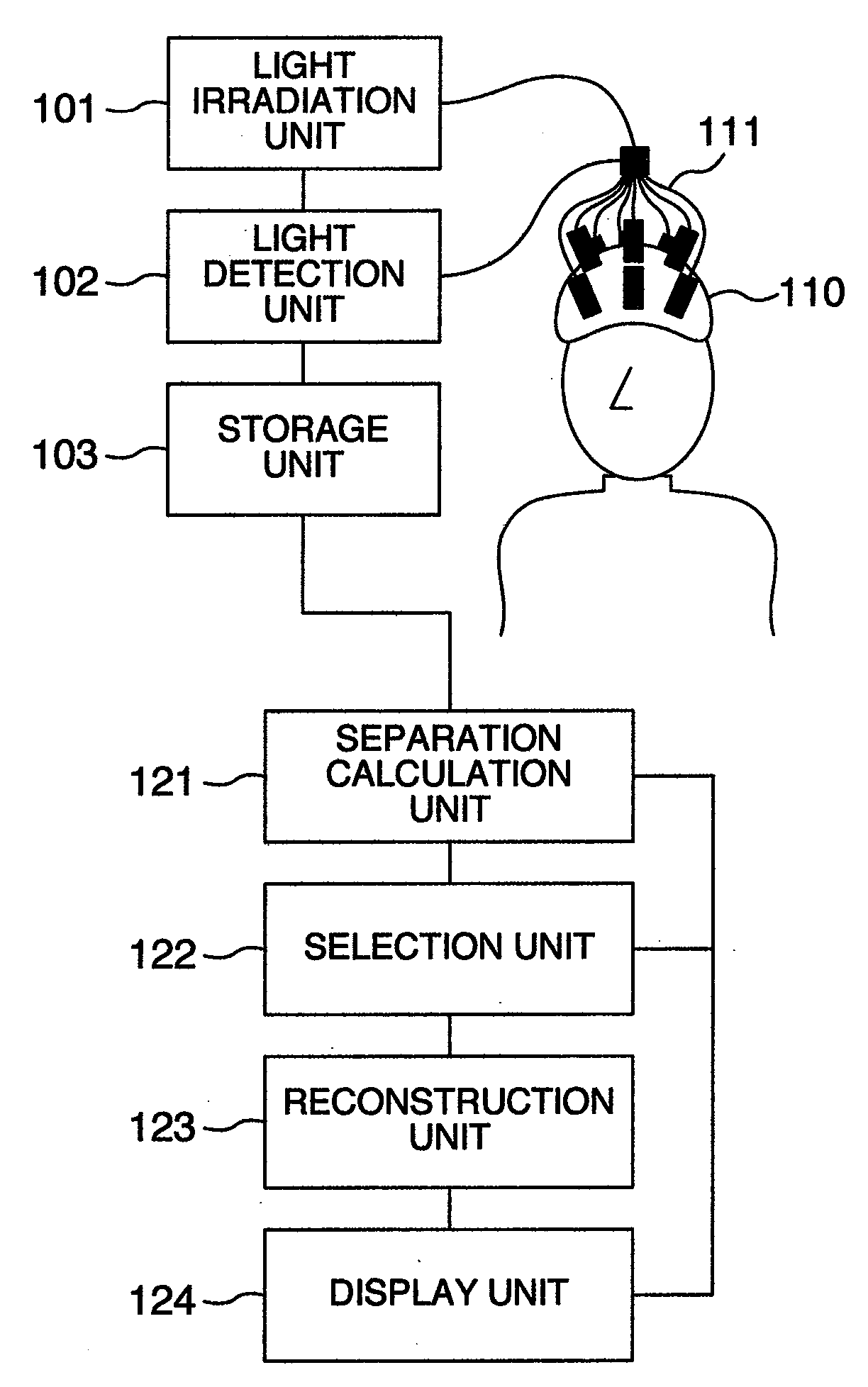
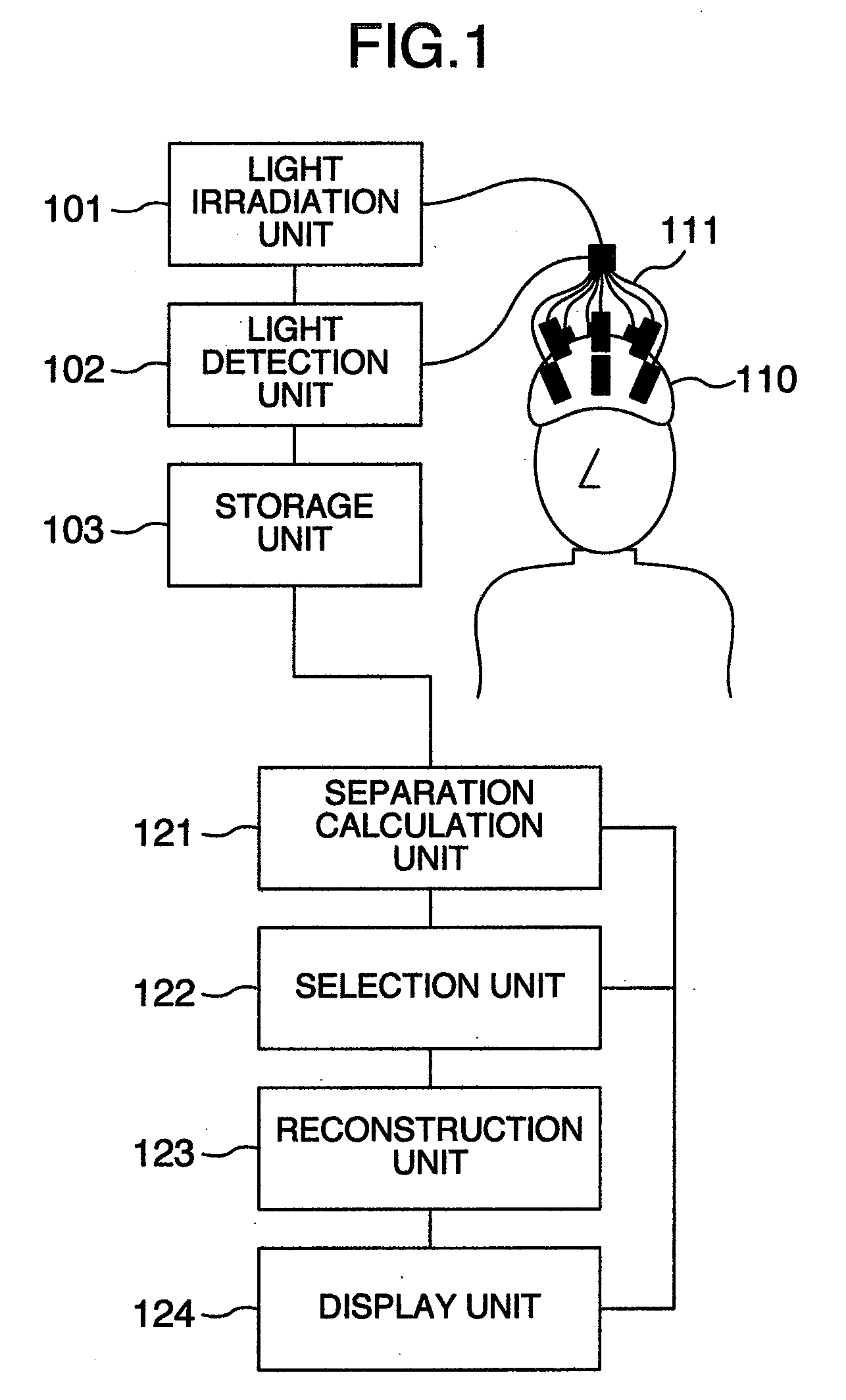
[0028]A specific block diagram is shown in FIG. 1 as an embodiment. An interface unit (110) for optical measurement of a living body is attached to part of or the whole of the head of a subject being tested. A light irradiation unit (101) irradiates the living body with mixed lights of 690 nm and 830 nm wavelengths through an optical fiber (111) coupled to the interface unit (110). The lights of each wavelength, which passed through the living body via the optical fiber (111) coupled to the interface unit (110), are detected by a light detection unit (102), and the detection result is stored in a storage unit (103). Here, light of other wavelengths may also be irradiated, and the number of combination of wavelengths employed may be three or more. Moreover, the obtained optical signals may be employed to the processing described in the following sections, after they are subjected to some sort of calculation processing.

[0029]Next, the optical signals are separated by a separation calc...


PUM


Abstract

An optical measurement instrument for living body that comprises: a plurality of light irradiation means for irradiating an object being tested with light; a plurality of light reception means for detecting the light that is irradiated to the object being tested and propagates inside the object being tested; and a calculation unit for calculating hemodynamics of a plurality of factors inside the object being tested from the detection signal detected by the light reception means, wherein the calculation unit comprises: a separation calculation unit for separating a plurality of signals from the detection signals; a selection unit for calculating a correlation coefficient between a plurality of the signals separated to select a signal in which a correlation coefficient is a predetermined value or greater as a noise signal; and a reconstruction calculation unit for reconfiguring the detection signal excluding the noise signal selected by the selection unit.

Description

INCORPORATION BY REFERENCE[0001]The present application claims priority from Japanese application JP2006-337737 filed on Dec. 15, 2006, the content of which is hereby incorporated by reference into this application.BACKGROUND OF THE INVENTION[0002]The present invention relates to an optical measurement technology, and particularly to an optical measurement method and instrument for receiving optical signals from a living body to obtain information on the living body. More particularly, the present invention relates to removing noise signals superimposed on the information on the living body to highly precisely obtain desired living body signals.[0003]Besides targeted signals, there are also noise signals, which are caused by several factors, included in measurement signals that are obtained by measuring information inside the living body using light (e.g., Patent Document 1). An averaging method, a band-pass filter, and the like are used to reduce the effects from the noise signals....

Claims


Application Information

Patent Timeline
Patent Type & Authority Applications(United States)
IPC IPC(8): A61B5/1455
CPCA61B5/0059A61B5/02028G06K9/6243A61B5/7207A61B5/6814G06F18/21343
Inventor KATURA, TAKUSIGETANAKA, NAOKIMAKI, ATSUSHI
Owner HITACHI LTD
Why Eureka
Try Eureka