Rapid-exchange balloon catheter shaft and method

Inactive Publication Date: 2008-06-19
CARDINAL HEALTH SWITZERLAND 515 GMBH
View PDF46 Cites 118 Cited by
  • Summary
  • Abstract
  • Description
  • Claims
  • Application Information

AI Technical Summary

Problems solved by technology

Such a stenosis may cause heart attack or stroke, which are significant health problems affecting millions of people each year.

Method used


Image

  • Rapid-exchange balloon catheter shaft and method
  • Rapid-exchange balloon catheter shaft and method
  • Rapid-exchange balloon catheter shaft and method

Examples


Embodiment Construction

[0041]The following description of the preferred embodiments of the present invention is merely illustrative in nature, and as such it does not limit in any way the present invention, its application, or uses. Numerous modifications may be made by those skilled in the art without departing from the true spirit and scope of the invention.

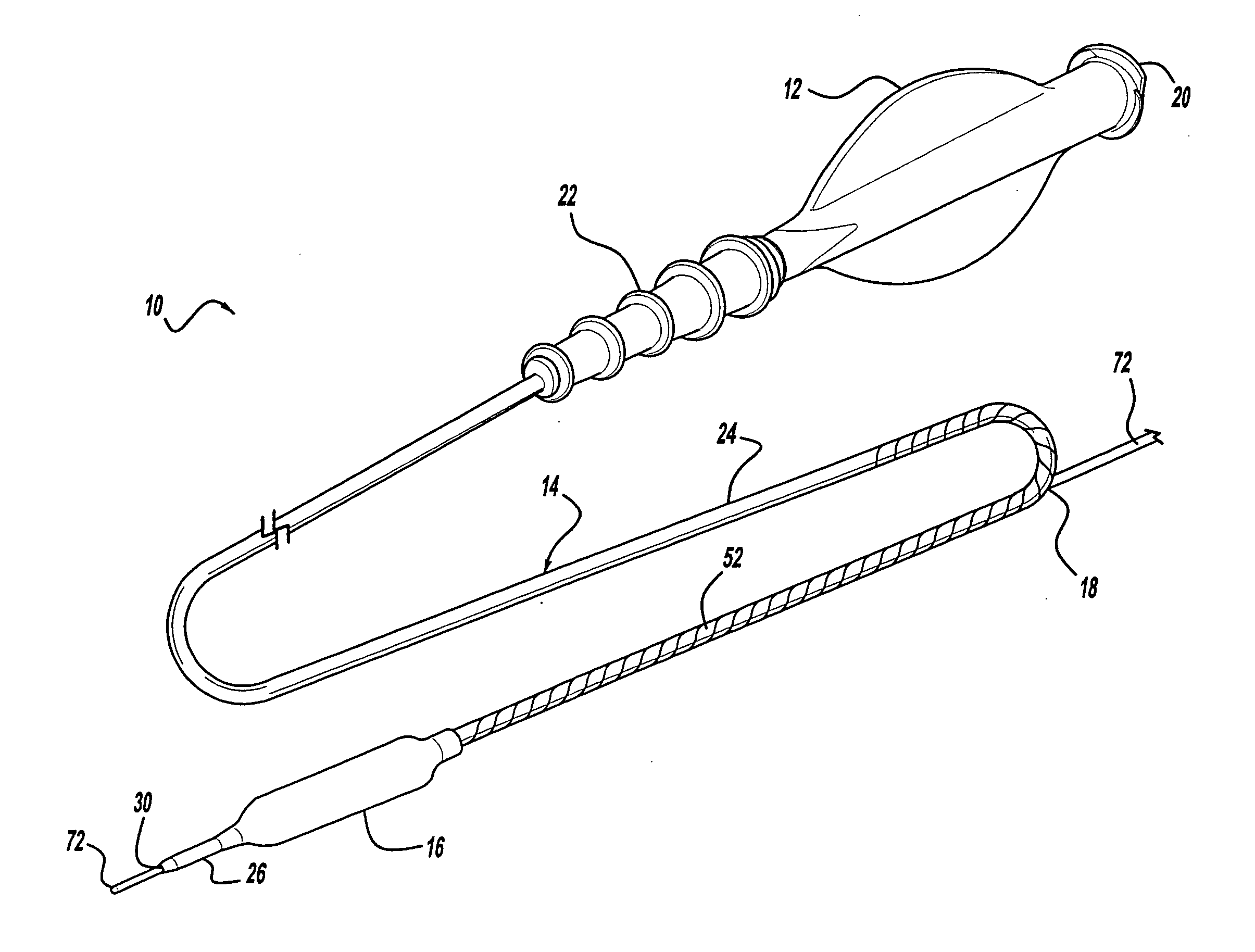
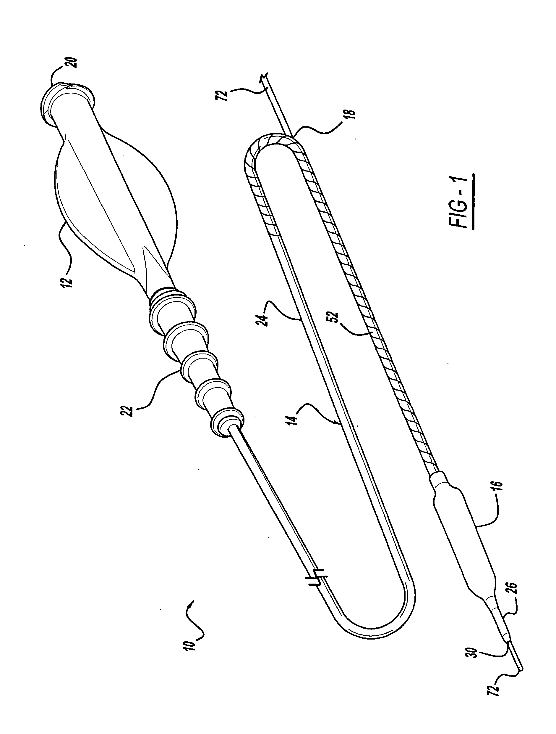
[0042]Referring to the drawings, a balloon catheter and stent delivery system are depicted, with an embodiment of the present invention being shown generally at 10. The illustrated balloon catheter and stent delivery system of course illustrate only some of many different designs within the scope of the present invention.

[0043]FIG. 1 shows an embodiment of the present invention, and includes a proximal hub 12, a flexible catheter shaft 14, and a balloon 16. An intermediate portion of the shaft defines a proximal guidewire port 18. The proximal hub 12 preferably provides an operating handle for a physician, and an inflation port 20. A tubular strain r...


PUM


Abstract

A balloon catheter or stent delivery system for medical treatment of a patient has a proximal hub, a balloon, and an improved shaft design. The catheter shaft has a rapid-exchange configuration, and a tubular outer body that includes a hypotube extending from the catheter proximal end to a position at or near a proximal leg of the balloon. An inner tubular body defines a guidewire lumen extending from a distal guidewire port at the catheter distal end to a proximal port located at a position between the balloon and the hub. A distal leg of the balloon is directly or indirectly affixed to the inner body, and a proximal leg of the balloon is affixed to the distal end of the outer body. The hypotube has an aperture for accepting the inner body proximal end, and a circumferential cut pattern. The cut pattern adds flexibility, and may extend from the hypotube distal end to a position proximal of the proximal guidewire port. The cut pattern may have any desired shape, including a spiral, a helical undulating path, or an overlapping serpentine path with inflection points, for example. The hypotube has a fluid-tight covering such as a heat-shrink polymer, so the outer body supports pressure of an inflation medium. The proximal guidewire port may be positioned on or between the individual portions of the cut pattern, or at a position beyond the cut pattern.

Description

CROSS-REFERENCE TO RELATED APPLICATION[0001]This application claims priority of U.S. Provisional Patent Application No. 60 / 880,000 filed Jan. 11, 2007, and U.S. Provisional Patent Application No. 60 / 930,471 filed May 16, 2007. This application is a continuation-in-part of U.S. patent application Ser. No. 10 / 691,823 filed Oct. 23, 2003, which is a continuation-in-part of U.S. Pat. No. 7,128,718 issued Oct. 31, 2006, which claims priority of U.S. Provisional Patent Application No. 60 / 366,739 filed Mar. 22, 2002.BACKGROUND AND SUMMARY OF THE INVENTION[0002]1. Technical Background[0003]This invention relates to medical devices, and more specifically to rapid-exchange balloon catheters or stent delivery systems with improved shaft designs.[0004]2. Discussion[0005]Catheter systems are used in a variety of therapeutic applications, including many vascular treatments. Various types of catheters are available, such as balloon catheters for procedures such as angioplasty. Angioplasty can be u...

Claims


Application Information

Patent Timeline
Patent Type & Authority Applications(United States)
IPC IPC(8): A61M25/10A61F2/84
CPCA61F2/915A61F2/958A61F2002/91558A61F2230/0054A61M25/0054A61M25/10A61M2025/0183A61F2250/0018
Inventor AL-MARASHI, LAILAGREWE, DAVIDGRIFFIN, STEPHENLIM, ELAINEMAJERCAK, DAVIDSTEVENS, ROGER
Owner CARDINAL HEALTH SWITZERLAND 515 GMBH
Why Eureka
Try Eureka