Motion control device for vehicle

a technology of motion control device and vehicle, which is applied in the direction of process and machine control, instruments, cycle equipment, etc., can solve the problems of insufficient influence reduction and insufficient influence reduction, and achieve the effect of reducing the influence of vibration and enhancing the accuracy of the motion control device in detecting the behavior of the vehicl

Inactive Publication Date: 2008-06-19
ADVICS CO LTD
View PDF23 Cites 8 Cited by
  • Summary
  • Abstract
  • Description
  • Claims
  • Application Information

AI Technical Summary

Benefits of technology

[0011]Accordingly, it is a primary object of the present invention to provide an improved motion control device for a vehicle which is capable of reducing the influence that the vibration gene

Problems solved by technology

However, it is unable to sufficiently reduce the influence that the vibration generated by the actuation of a pump (of a reciprocation type) being a hydraulic device exerts on a yaw rate sensor.

Method used


Image

  • Motion control device for vehicle
  • Motion control device for vehicle
  • Motion control device for vehicle

Examples


first embodiment

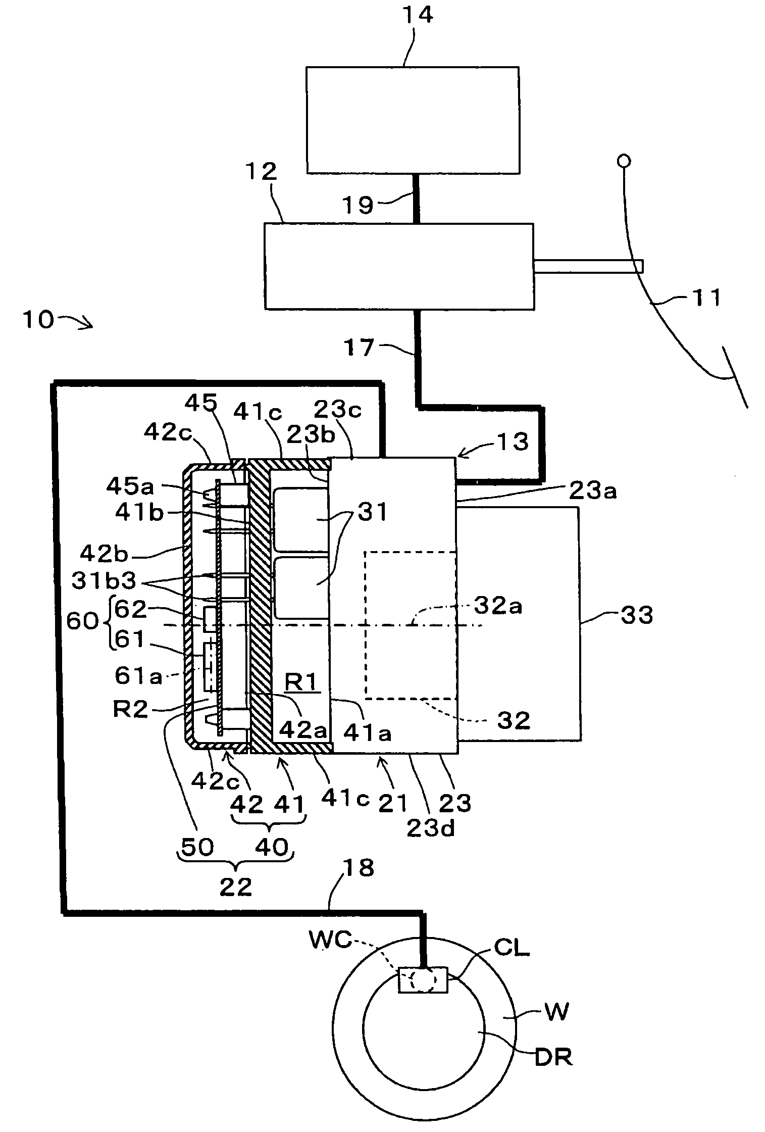
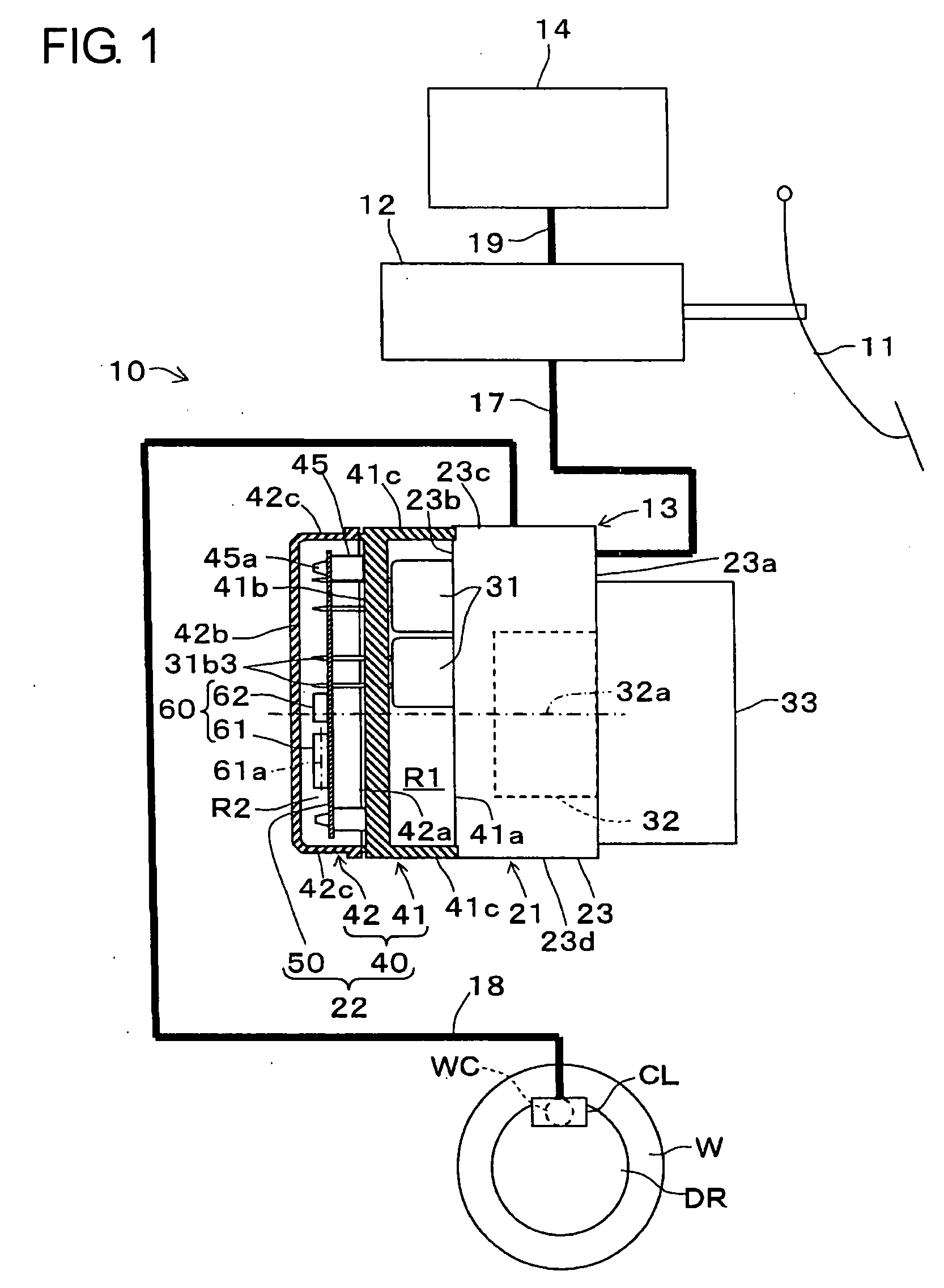
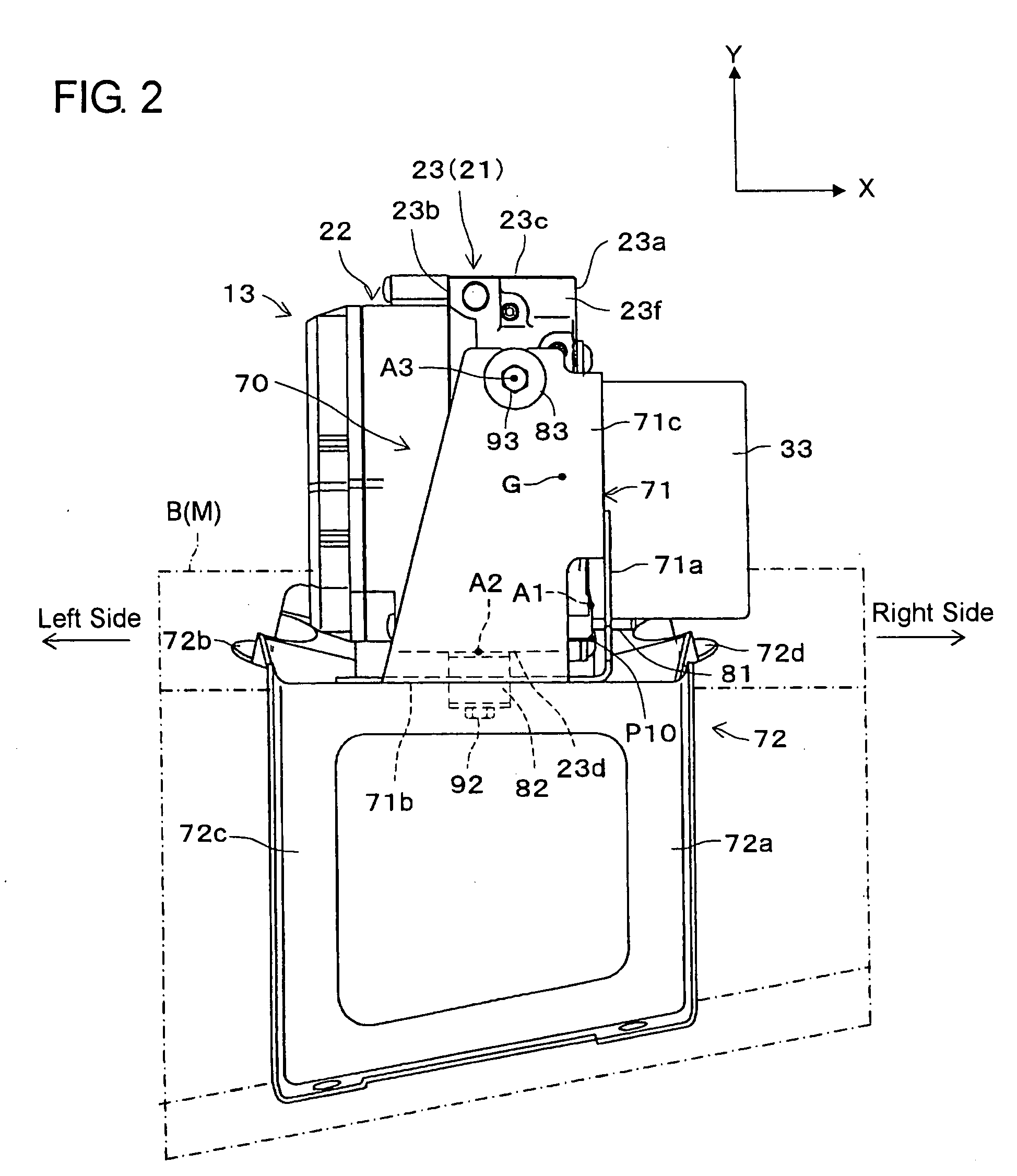
[0025]Hereinafter, a first embodiment of a motion control device for a vehicle according to the present invention will be described with reference to the accompanying drawings. FIG. 1 is a schematic view showing a hydraulic brake system 10 incorporating the motion control device 13. FIGS. 2 to 4 are a front view, a top view and a side view each showing the motion control device 13 which is supported on a vehicle body B of a vehicle M through a bracket 70.

[0026]The hydraulic brake system 10 applies brake forces to wheels W (one only shown for brevity) of the vehicle M. As shown in FIG. 1, the hydraulic brake system 10 is provided with a master cylinder 12, wheel cylinders WC (one only shown for brevity), the motion control device 13 and a reservoir tank 14.

[0027]The master cylinder 12 generates a hydraulic pressure (base hydraulic pressure) depending on a brake manipulation state which is brought about by the stepping of a brake pedal 11, and applies the hydraulic pressure to the whe...

second embodiment

[0089]Instead of being applied to a motion control device with a rotary pump for a vehicle, the present invention may be applied to a motion control device with a piston pump. This modification or second embodiment will then be described with reference to FIGS. 8 to 10. FIG. 8 is a schematic front view, partly in section, of a hydraulic brake system 10 to which a motion control device 13 provided with a piston pump 132 for a vehicle M is applied. FIG. 9 is a right side view of the hydraulic brake system 10, and FIG. 10 is a fragmentary sectional view showing the piston pump 132.

[0090]Specifically, the pump 132 being as piston pump is composed of a pump drive section 132b drivingly rotated by the motor 33 and a plurality (e.g., two in this particular embodiment) of pumping sections 132c which perform a pump function with rotation of the pump drive section 132b.

[0091]As shown mainly in FIGS. 9 and 10, the pump drive section 132b is provided with an eccentric cam 132b1 which is couple...


PUM


Abstract

A motion control device for a vehicle is configured so that a hydraulic unit mounting therein a pump for generating a controlled hydraulic pressure applied to respective wheel cylinders of the vehicle is integrated with a control unit provided with a yaw rate sensor for detecting a yaw rate of the vehicle and capable of controlling the hydraulic unit. The pump is composed of a pump drive section, drivingly rotated by a motor, and pumping sections which perform a pump function with the rotation of the pump drive section. The yaw rate sensor, the motor and the pump are arranged to satisfy a positional relation that the extending direction of a detection axis of the yaw rate sensor does not coincide with both of the extending directions of a rotational axis of the motor and a rotational axis of the pump drive section.

Description

INCORPORATION BY REFERENCE[0001]This application is based on and claims priority under 35 U.S.C. 119 with respect to Japanese Applications No. 2006-339980 filed on Dec. 18, 2006 and No. 2007-291864 filed on Nov. 9, 2007, the entire contents of which are incorporated herein by reference.BACKGROUND OF THE INVENTION[0002]1. Field of the Invention[0003]The present invention relates to a motion control device for a vehicle which integrally incorporates a hydraulic unit mounting therein a pump for generating a controlled hydraulic pressure applied to respective wheel cylinders of the vehicle and a control unit provided with a yaw rate sensor for detecting the yaw rate of the vehicle and capable of controlling the hydraulic unit.[0004]2. Discussion of the Related Art[0005]Heretofore, there has been known a motion control device for a vehicle which is shown in International Publication WO 2005 / 039946 A1 (hereafter referred to as Patent Document 1). As shown in FIGS. 1 and 2 of Patent Docume...

Claims


Application Information

Patent Timeline
IPC IPC(8): G06F19/00
CPCB60T8/171B60T8/368B60T17/02B60T8/4031B60T8/3685
Inventor KAMIYA, MASAHIKOUSAMI, TADAYOSHI
Owner ADVICS CO LTD
Why Eureka
Try Eureka