
Communication apparatus and control method thereof

a technology of communication apparatus and control method, applied in the field of communication apparatus, can solve the problems of increasing workload, unauthorized access cannot be prevented, and the vulnerability of network security to unwanted remote access or attacks from external devices, so as to reduce the amount of labor required

Inactive Publication Date: 2008-06-19
CANON KK
View PDF3 Cites 13 Cited by
  • Summary
  • Abstract
  • Description
  • Claims
  • Application Information

AI Technical Summary

Benefits of technology

[0009]Another aspect of the present invention is to, in a case that an address of an external device for which reception is to be refused or permitted is registered, reliably refuse or permit reception from the external device by preventing a registration omission or a registration error of the address of the external device.
[0010]Yet another aspect of the present invention is to reduce labor required to register the address of the external device.

Problems solved by technology

With the spread of the Internet in recent years, there has been concern over the vulnerability of network security to unwanted remote access or attacks from external devices, packet interception, and so on.
However, conventional network device filtering technologies such as these have increased the workload since in a case where an external device has a plurality of addresses, a user is required to set all the addresses of the external devices as targets to be filtered.
Also, there has been a problem in that in a case that a plurality of addresses are registered manually, a registration omission or a registration error may occur, causing a certain external device not to be treated as a target to be filtered, and resulting in a situation in which an unauthorized access cannot be prevented.
Above all, since conventional filtering technologies have been established assuming only the use of IPv4 addresses, the application of these technologies is difficult in a case where the address length is long and a plurality of addresses is handled, as is the case with IPv6 addresses, the use of which is expected to spread.

Method used


Image

  • Communication apparatus and control method thereof
  • Communication apparatus and control method thereof
  • Communication apparatus and control method thereof

Examples


first embodiment

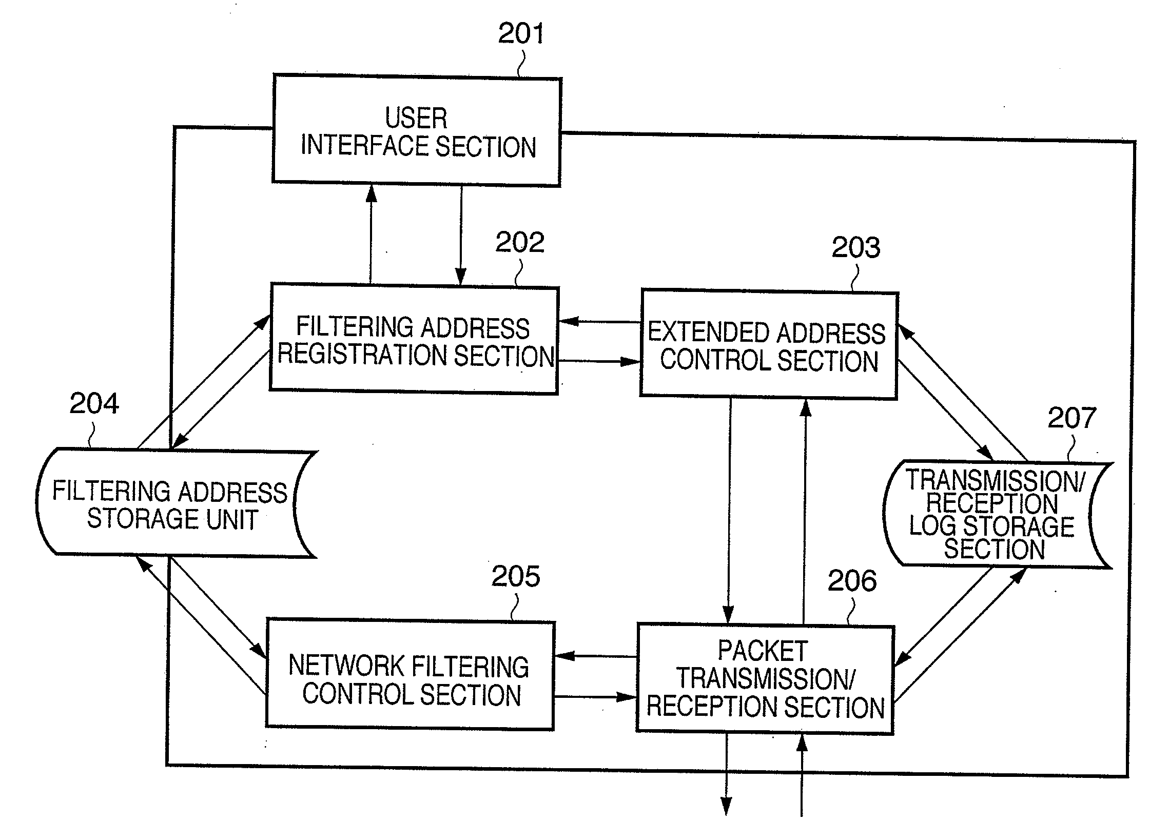
[0057]FIG. 6 is a flowchart explaining a process of the digital multi function peripheral 100 according to a first embodiment in a case that the user interface section 201 sets address information of a single external device as a filtering target. The sequence described here is when an additional IP address related to the address information is obtained as well by using the DNS server 307 and the obtained IP address is also set as a filter target.

[0058]First, in step S1, the filtering address registration section 202 receives an IP address to be filtered from the user interface section 201. At this time, in the user interface section 201, any IP address, whether it is an IPv4 address or an IPv6 address, can be entered. In the present embodiment, as shown in FIG. 7, an IPv4 address “169.10.0.2” of the external device 302 is registered as a filtering target address so that connection from the external device 302 is refused.

[0059]FIG. 7 depicts a view illustrating an example of a scree...

embodiment 2

[0077]FIG. 11 is a flowchart explaining a process of the digital multi function peripheral 100 according to a second embodiment of the present invention in a case that the user interface section 201 sets an address of a single external device as a filtering target. In this example, a MAC address of the external device is obtained by transmitting a ping command to a registered IP address, and the obtained MAC address is applied to a MAC address filter so that filtering is performed on a physical layer level. Note that since the multi function peripheral 100, its software configuration, its network configuration, and so on in the second embodiment are the same as in the first embodiment, explanations thereof shall be omitted. The ping command is a command that transmits small-sized packet data to a destination over a TCP / IP network such as the Internet to check the state of a communication line based on a return time of a response to the packet data.

[0078]First, in step S11, the filte...

embodiment 3

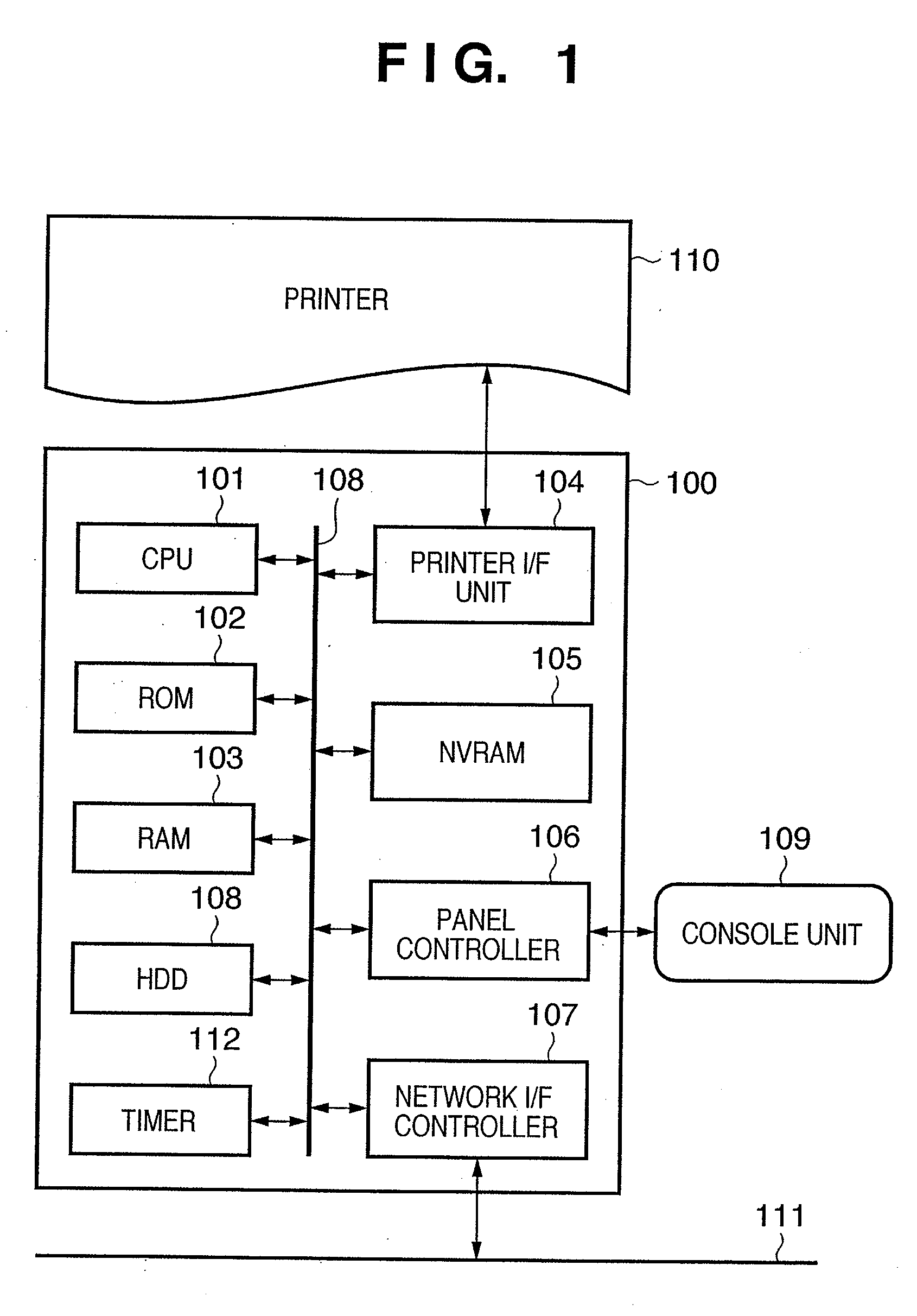
[0093]FIG. 14 is a flowchart explaining a process of the digital multi function peripheral 100 according to a third embodiment of the present invention in a case that a user sets an address of an external device as a filtering target using the user interface section 201. It should be noted that since the multi function peripheral 10, its software configuration, its network configuration, and so on in the third embodiment are the same as that of the first embodiment, explanations thereof will not be given.

[0094]The process shown in FIG. 14 represents a process in which filtering is performed on a physical layer level by obtaining a MAC address of an external device with the use of the transmission / reception log storage section 207 and by storing the obtained MAC address in the filtering address storage unit 204.

[0095]First, in step S21, the filtering address registration section 202 enters the IP address to be filtered from the user interface section 201. At this time, in the user in...


PUM


Abstract

Address information of an external device is registered as address information to refuse reception or to permit reception in a filtering address storage unit, and additional address information held by an external device having the registered address information is obtained. Then, the obtained additional address information is registered in association with the address information in the filtering address storage unit. In a case that information is received from an external device, it is determined whether or not the address information of the external device is stored in the storage unit so that information from the external device is refused.

Description

BACKGROUND OF THE INVENTION[0001]1. Field of the Invention[0002]The present invention relates to a communication apparatus that is connected to a network and that is provided with an address filtering function, and a control method thereof.[0003]2. Description of the Related Art[0004]With the spread of the Internet in recent years, there has been concern over the vulnerability of network security to unwanted remote access or attacks from external devices, packet interception, and so on. As a measure against this, network devices are generally provided with functionality for filtering unwanted access from an external device using an IP address or a physical address. With this kind of filtering function, a user registers a specific address s / he wishes to refuse in advance; security is guaranteed by refusing access from an external device that has the registered address (Japanese Patent Laid-Open No. 2002-152279).[0005]In some of such filtering functions, IP addresses from which recept...

Claims


Application Information

Patent Timeline
Patent Type & Authority Applications(United States)
IPC IPC(8): G06F15/16
CPCH04L29/12066H04L29/12952H04L63/0236H04L61/6077H04L61/1511H04L61/4511H04L2101/677G06F15/16G06F12/00
Inventor INOUE, GO
Owner CANON KK
Learn More