Matching circuit and dual-band power amplifier

a matching circuit and power amplifier technology, applied in amplifiers with semiconductor devices/discharge tubes, multi-port networks, transmission, etc., can solve the problems of increasing the size of the device, the difficulty of designing such a circuit that is optimized, and the increase of the number of components such as the input and output matching circuit,

Inactive Publication Date: 2008-06-26
NTT DOCOMO INC
View PDF3 Cites 8 Cited by
  • Summary
  • Abstract
  • Description
  • Claims
  • Application Information

AI Technical Summary

Benefits of technology

[0017]In the above configuration, by constructing the series matching block as a transmission line of the characteristic impedance Z0, the line length may be arbitrarily set at the first frequency. This also makes it possible to set the length of the transmission line of the series matching block and the reactance value of the third parallel matching block, at the second frequency f2, which is different from the first frequency, without changing the matching condition at the first frequency.
[0019]In the above configuration, the series matching block is capable of setting any one of one or more impedance conversion quantities, the third parallel matching block is capable of setting any one of one or more reactance values, there are at least N combinations that can be selected from the impedance conversion quantities and the reactance values, and the above combinations correspond to the second frequencies, on a one-to-one basis. The combination of the impedance conversion quantity and the reactance value corresponding to the second frequency f2, which is different from the first frequency, is set in the series matching block and the third parallel matching block, respectively. It is therefore possible to configure the matching circuit capable of effecting impedance matching simultaneously or selectively for a signal of the first frequency f1 by the main-matching block and the series matching block, and for a signal of arbitrarily selected one of N second frequencies f2 which are different from the first frequency.

Problems solved by technology

It is therefore difficult to design such a circuit that is optimized for both of the aforementioned two different frequency bands, for example.
This causes a problem that the number of components such as the input and output matching circuits, amplification devices, etc will be increased.
The increased number of the components also causes other problems that the device size is increased, and in addition, the power consumption in the whole circuit is increased by the power consumption in each component.
In addition, there is another problem that the output power is lowered by the insertion loss of the SPDT switch used for output in particular, thereby decreasing the efficiency.
This has a drawback of increasing the circuit size (see Japanese Patent Application Laid Open No. 2003-504929, for example).

Method used


Image

  • Matching circuit and dual-band power amplifier
  • Matching circuit and dual-band power amplifier
  • Matching circuit and dual-band power amplifier

Examples


first embodiment

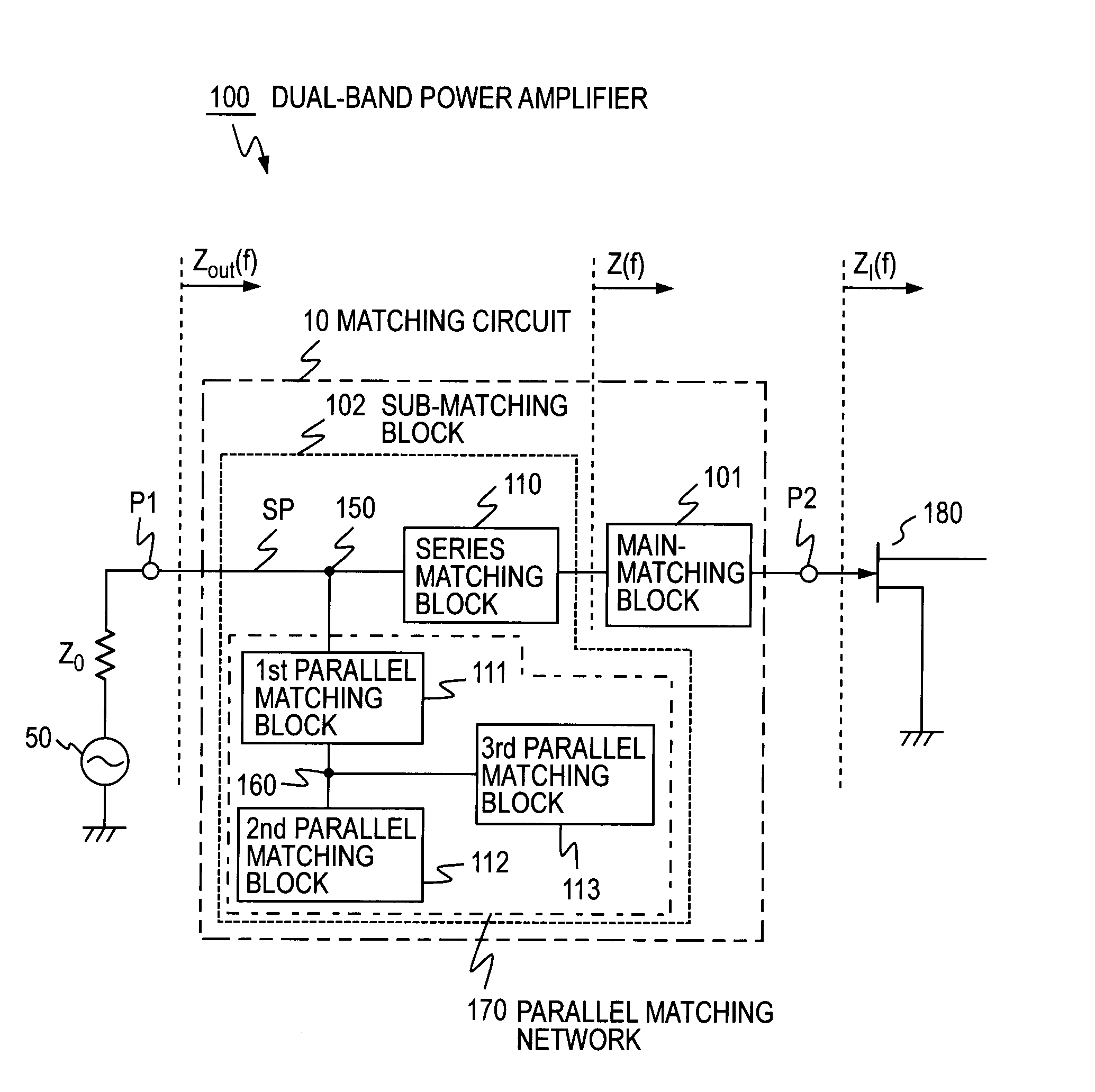
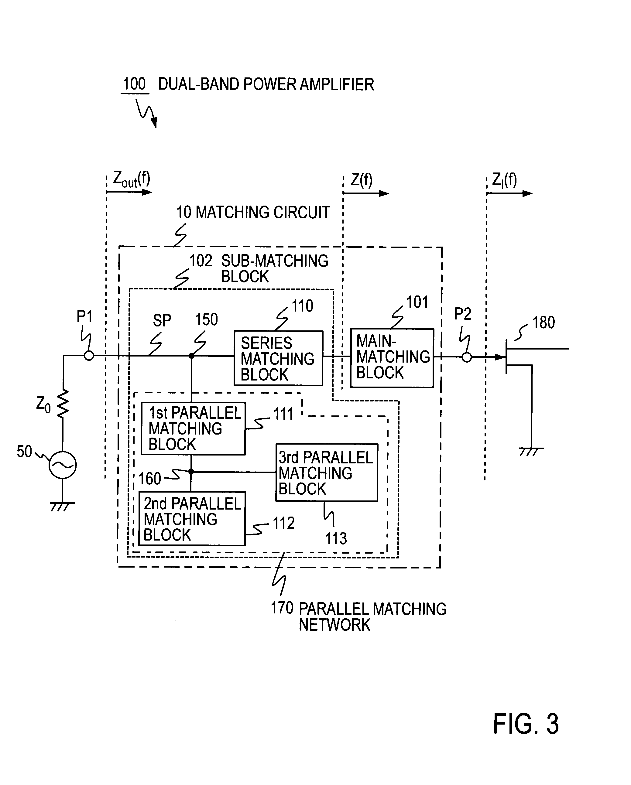
[0042]FIG. 3 illustrates a matching circuit 10 according to the first embodiment. FIG. 3 also illustrates the configuration of an input-side circuit of a dual-band power amplifier 100 which can amplify signals of the two frequency bands of FIG. 14 selectively or simultaneously. The first embodiment is an example where the matching circuit 10 is used on the input terminal side of an amplification device 180. In this context, “can amplify selectively” means that even when either one of the signals of two frequency bands is inputted, it is possible to amplify the signal. “can amplify simultaneously” means that signals of two frequency bands are inputted at the same time, in other words, a combined signal of the two frequency bands can be amplified in the respective frequency bands simultaneously. The same applies to the following description.

[0043]Generally, matching circuits are those for establishing matching between different impedances. An example thereof is to perform impedance ma...

second embodiment

[0067]The first embodiment has exemplarily described the dual-band power amplifier 100 capable of amplifying the signals of the two frequency bands selectively or simultaneously as well as the matching circuit 10 that performs impedance matching on the signals of the two frequency bands selectively or simultaneously. The second embodiment, as an expansion of the first embodiment, will exemplarily describe the dual-band power amplifier 100 capable of amplifying two out of N+1 signals of predetermined frequency bands SB1 to SBN+1, where N assumes an integer of 2 or more, as shown in FIG. 15, as well as the matching circuit 10 that performs impedance matching.

[0068]In the first embodiment previously described, the electric length of the series matching block 110 configured as a transmission line and the reactance value of the third parallel matching block 113 are designed for the second frequency f2 without changing the matching condition at the first frequency f1. The second embodimen...

third embodiment

[0078]The third embodiment, as an expansion of the first embodiment but different from the second embodiment, will exemplarily describe the dual-band power amplifier capable of amplifying two signals out of signals of three or more frequency bands, selectively or simultaneously, as well as the matching circuit that performs impedance matching on signals of two frequency bands, selectively or simultaneously.

[0079]FIG. 11 illustrates the matching circuit 10 according to the third embodiment. FIG. 11 also illustrates the circuit configuration of the dual-band power amplifier 100 capable of amplifying a signal of the first frequency f1 and a signal of another frequency in one of N+1 frequency bands shown in FIG. 15, selectively or simultaneously, where N assumes an integer of 2 or greater. The third embodiment is an example where the matching circuit 10 is used on the input terminal side of the amplification device 180.

[0080]The outline of the matching circuit 10 according to the third ...


PUM


Abstract

There is provided a matching circuit, in which a main-matching block and a sub-matching block are connected in series. The sub-matching block includes: a series matching block of which one end is connected to the main-matching block; and a parallel matching network connected to the other end of the series matching block. At a first frequency f1, the connection point of the series matching block and a first parallel matching block is caused to be in an open state for a radio-frequency signal, and the connection point of the first parallel matching block and the second parallel matching block is caused to be in a short state for the radio-frequency signal. Impedance matching is performed by the main-matching block and the series matching block at the first frequency f1, and is performed by the main-matching block and the sub-matching block at the second frequency f2.

Description

TECHNICAL FIELD[0001]The present invention relates to a matching circuit and a power amplifier using the matching circuit.BACKGROUND ART[0002]In recent years, with diversification of services provided by radio communication, there is a demand for multiband operation in radio equipment capable of dealing with information in plural frequency bands. For example, two frequency bands, which are 5.2 GHz and 2.4 GHz bands, are specified in the respective standards of Institute of Electrical and Electronic Engineers (IEEE) 802.11a / b / g that are the technical standards of wireless Local Area Network (LAN).[0003]As one of the devices implemented in the radio equipment, a power amplifier is used that amplifies signals of a radio frequency band and supplies the signals to an antenna. A power amplifier is one of such devices that consume a large amount of power in a radio circuit, and are required to operate at a high efficiency. Generally, in the design of a radio circuit, optimization has been ...

Claims


Application Information

Patent Timeline
Patent Type & Authority Applications(United States)
IPC IPC(8): H03F3/60H03H7/38
CPCH03F1/56H03F3/191H03F3/60H03F2200/111H03F2200/222H04B1/0458H03F2200/255H03F2200/423H03H7/38H04B1/0053H03F2200/252H03F3/20
Inventor FUKUDA, ATSUSHIOKAZAKI, HIROSHINARAHASHI, SHOICHI
Owner NTT DOCOMO INC
Why Eureka
Try Eureka