
Security Sensor-Transmitter for Detecting Wind in a Home Automation Installation

a technology of security sensor and transmitter, which is applied in the field of security sensor transmitter, can solve the problems of difficult adjustment of setting potentiometer, difficult replacement of battery, and difficulty in automatic movement, so as to facilitate and reduce the risk of setting operations. , the effect of simple structur

Active Publication Date: 2008-06-26
SOMFY ACTIVITES SA
View PDF10 Cites 9 Cited by
  • Summary
  • Abstract
  • Description
  • Claims
  • Application Information

AI Technical Summary

Benefits of technology

[0015]The aim of the invention is to provide a sensor-transmitter that obviates the abovementioned drawbacks and that enhances the sensors-transmitters known from the prior art. In particular, the invention proposes a sensor-transmitter with a simple structure which facilitates and makes less hazardous the setting operations, in particular the transmission threshold setting operations. The invention also relates to a learning method and an operating method of such a sensor-transmitter.

Problems solved by technology

Two problems posed by this type of sensor are the assignment of the setting thresholds (to adjust the sensor's sensitivity level) and the replacement of the battery.
In practice, it is important for the sensor to include a perfectly watertight casing, because the mobile structure, sensitive to the effects of the wind, is also subject to bad weather, humidity or salt fogs.
By its unexpected nature, this automatic movement can be particularly hazardous, for instance if the sensor is positioned on the load bar of a arm awning, and if the user, or installer has deployed the awning to access more easily the load bar using a stepladder.
Moreover, the adjustment of a setting potentiometer will be difficult if the latter is inside a closed casing.
Conversely, making the control of the potentiometer accessible from the outside would considerably increase the cost, because of the seal-tightness constraint.

Method used


Image

  • Security Sensor-Transmitter for Detecting Wind in a Home Automation Installation
  • Security Sensor-Transmitter for Detecting Wind in a Home Automation Installation
  • Security Sensor-Transmitter for Detecting Wind in a Home Automation Installation

Examples


Embodiment Construction

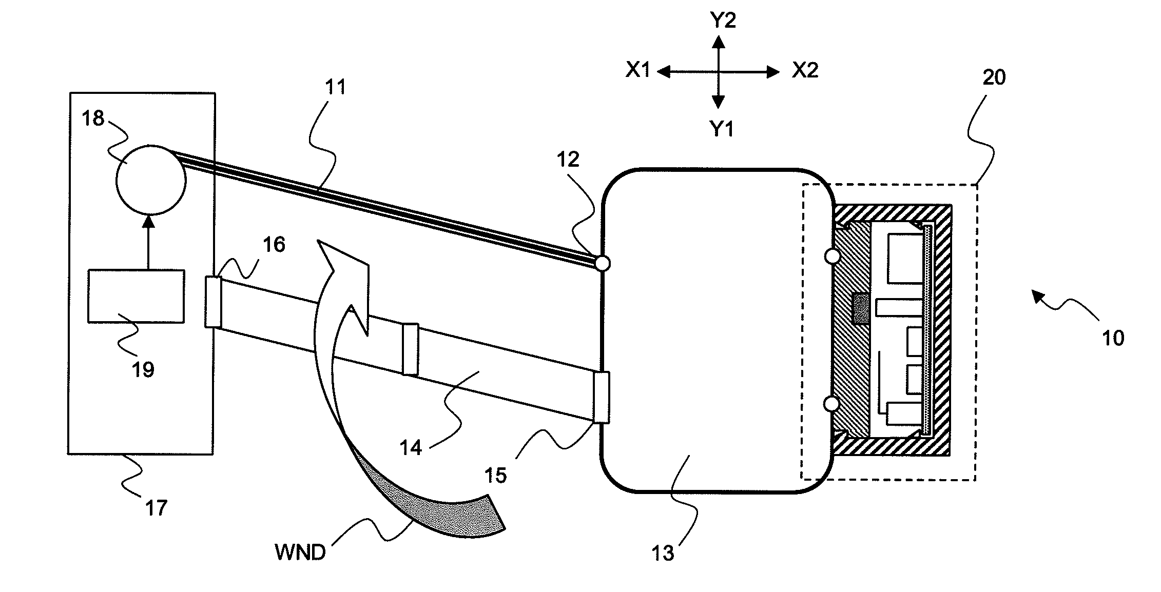
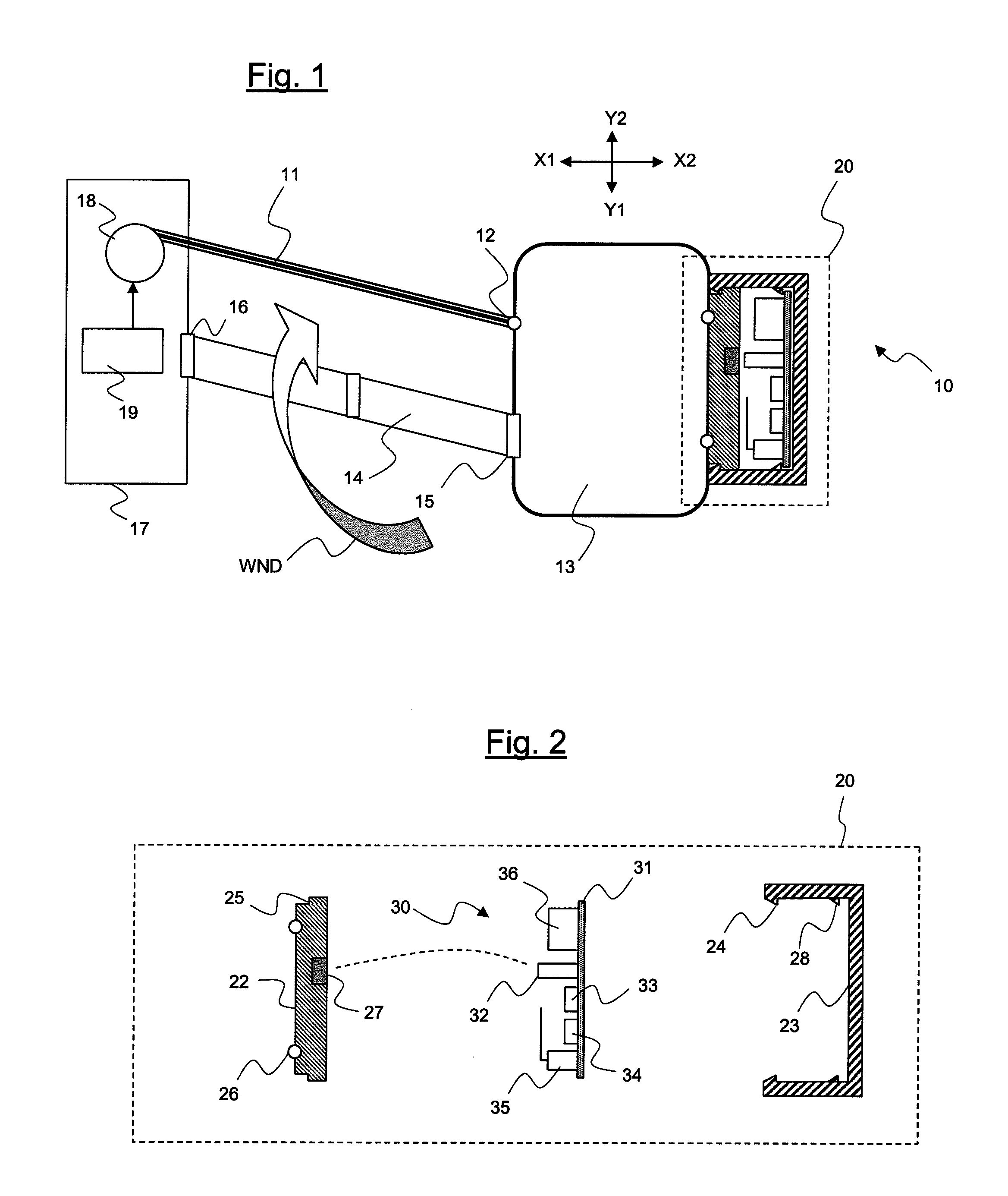
[0030]FIG. 1 represents an installation 10 comprising a motorized arm awning, the fabric 11 of which is attached by a fastening 12 to a load bar 13. The fabric winds onto a motorized tube 18. When the motor winds the fabric onto the winding tube, the latter provokes the movement of the load bar 13 in the direction X1 and, to a lesser extent, in the direction Y2. A plurality of articulated arms 14, provided with springs, make it possible to exert a force on the load bar 13 in the direction X2 and, to a lesser extent, in the direction Y1 so as to keep the fabric taut. The articulated arm 14 is connected to the load bar by a first articulation 15. The articulated arm comprises other articulations, in particular a second articulation 16 connecting it to the fixed structure 17 of the installation, which comprises the motorized winding tube. The load bar, fabric and articulated arms constitute the mobile structure.

[0031]The installation 10 also comprises a sensor-transmitter 20, fastened ...


PUM


Abstract

A sensor-transmitter (20) intended to be fastened to a mobile structure (11, 13, 14) and to transmit a security signal in a home automation installation (10), comprising, in a casing (22, 23): an autonomous power source (36), a vibration sensor (33), a wireless transmitter (35) and a processing logic unit (34) analyzing the signals obtained from the vibration sensor to decide whether to transmit the security signal by the wireless transmitter, which comprises means (27, 32) of detecting the mechanical state of the casing, the sensor-transmitter being:in an operational state when the casing is closed and fastened to the mobile structure, the transmission of a security signal being enabled in this operational state, andin a disabled state otherwise,the transmission of a security signal being prohibited in this disabled state, whereas the transmission of other signals remains possible, orthe transmission of a security signal being enabled in this disabled state, the security signal being disabled by a disabling signal.

Description

BACKGROUND OF THE INVENTION[0001]The invention relates to a security sensor-transmitter positioned on a motorized mobile structure in a home or building automation installation, in particular a motorized blind or awning, to a disabling method and to a learning method for such a sensor-transmitter. The sensor-transmitter includes a wireless transmitter so as to transmit a security signal.DESCRIPTION OF THE PRIOR ART[0002]The use of vibration sensors is known, comprising, for example, an accelerometer, for detecting the movements due to the wind on such a mobile structure. The sensor is fastened against the mobile structure, in a place where the effects of the wind are particularly important. It also comprises a device for analyzing signals obtained from the accelerometer, and a radio transmitter for sending to a motor control unit a awning retraction control when the level of vibrations exceeds a predetermined threshold.[0003]Such a device is known, for example, from patent applicati...

Claims


Application Information

Patent Timeline
IPC IPC(8): G08B13/20
CPCE04F10/0618E04F10/0659E04F10/0692G08C2201/51G01H1/00G01P13/00G08C17/02E06B2009/6863
Inventor GUILLEMOT, ERIC ANDRE GEORGESGREHANT, BERNARD
Owner SOMFY ACTIVITES SA
Learn More