Image processing apparatus and image pickup apparatus

Inactive Publication Date: 2008-06-26
CANON KK
View PDF12 Cites 18 Cited by
  • Summary
  • Abstract
  • Description
  • Claims
  • Application Information

AI Technical Summary

Benefits of technology

[0013]Further, an image processing method as still another aspect of the present invention includes the steps of detecting a shake in a first image area of an input image including a distortion, generating shake information on a shake in a second image area of

Problems solved by technology

However, the image stabilization disclosed in Japanese Patent Nos. 2,586,686 and 2,506,500 have problems as follows.
Due to the premise, the method can not realize image stabilization accuracy that is sufficient enough for an image including a distortion like an image picked up using a wide-angle lens and an image picked up using a lens such as a fish-eye lens of which projection method is not a perspective projection method.
Therefore, even though the predicted movement amount obtained

Method used


Image

  • Image processing apparatus and image pickup apparatus
  • Image processing apparatus and image pickup apparatus
  • Image processing apparatus and image pickup apparatus

Examples


embodiment 1

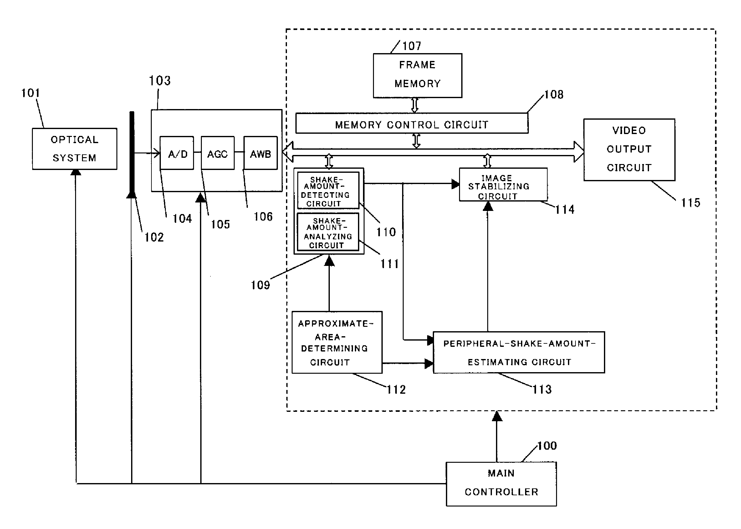
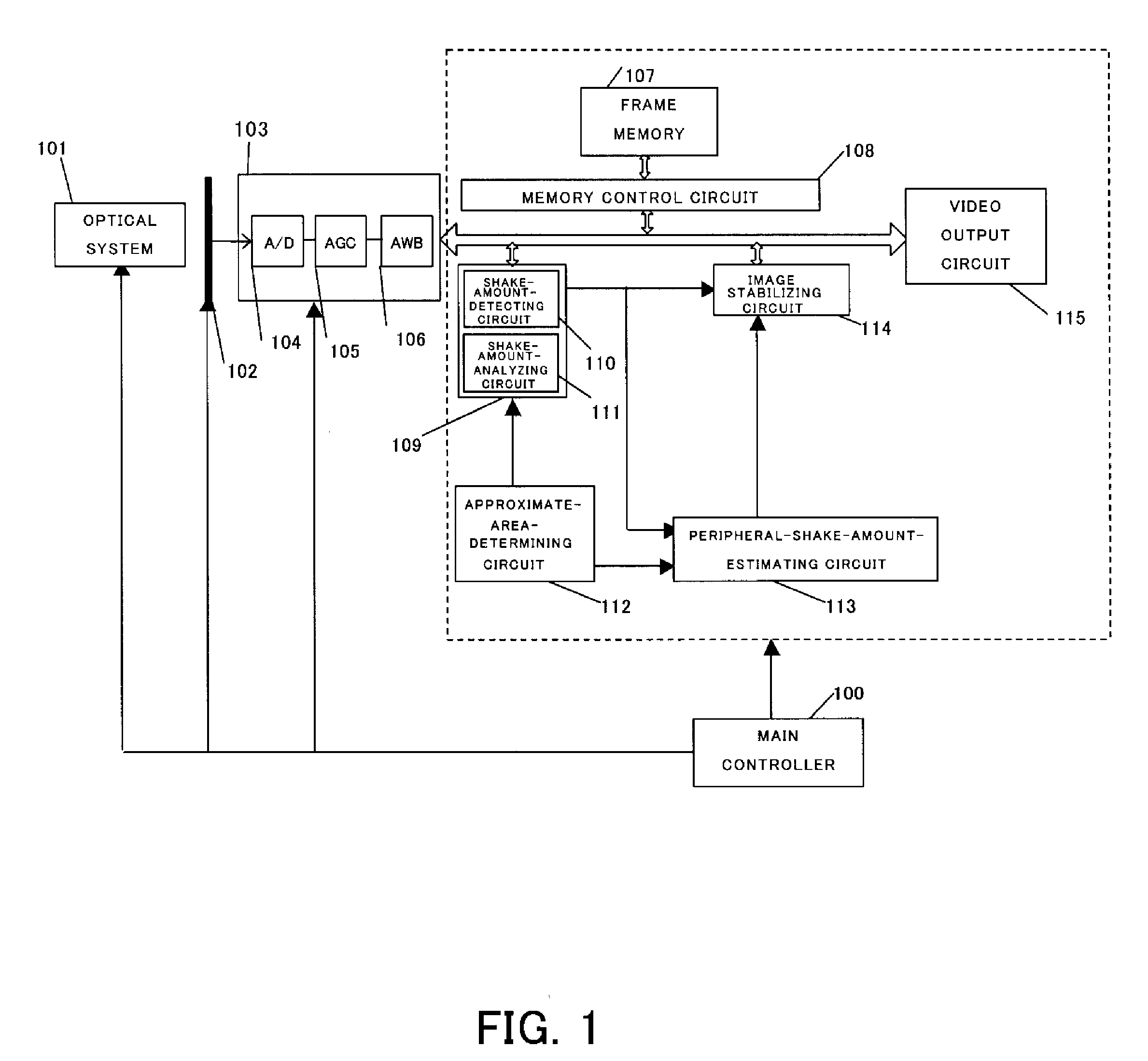
[0030]FIG. 1 shows the configuration of an image pickup apparatus that is Embodiment 1 according to the present invention. The image pickup apparatus includes an image pickup system and an image processing system (image processing apparatus) having an image-stabilizing function as described below.

[0031]In FIG. 1, reference numeral 101 denotes an optical system for forming an object image with a light flux from an object. Reference numeral 102 denotes an image pickup element such as a CCD sensor and a CMOS sensor that photoelectrically converts the object image formed by the optical system 101.

[0032]Reference numeral 103 denotes an image-generating part that generates a video signal from an electric signal output from the image pickup element 102. The image-generating part 103 includes an A / D converting circuit 104, an auto gain control circuit (AGC) 105 and an auto-white-balance circuit (AWB) 106, and generates a digital video signal.

[0033]The A / D converting circuit 104 converts an ...

embodiment 2

[0076]FIG. 5 shows the configuration of the image pickup apparatus that is Embodiment 2 according to the present invention. In this embodiment, the approximate-perspective-projection area is determined according to the size of the view angle of the input image.

[0077]An element in FIG. 5 common to that shown in FIG. 1 is designated with the same reference numeral.

[0078]The image pickup apparatus in this embodiment includes an input-view-angle-detecting circuit 516 that detects the view angle of the input image (referred to as input view angle hereinafter) as well as the configuration shown in FIG. 1. The main controller shown in FIG. 1 is omitted in FIG. 5.

[0079]Operations of the image pickup apparatus in this embodiment will be described using a flowchart shown in FIG. 6 as follows.

[0080]A step S601 is identical to the step S201 shown in FIG. 2 of Embodiment 1.

[0081]At a step S602, the input view angle is calculated by the input-view-angle-detecting circuit 516 based on position inf...

embodiment 3

[0089]FIG. 8 shows the configuration of the image pickup apparatus that is Embodiment 3 according to the present invention. In this embodiment, the approximate-perspective-projection area in the input image is determined, based on the magnitude change of the apparent shake amount (motion vector) on the input image.

[0090]An element in FIG. 8 common to that shown in FIG. 1 is designated with the same reference numeral.

[0091]The image pickup apparatus in this embodiment, having the configuration different from that in FIG. 1, determines the approximate-perspective-projection area by forwarding the detected result of the shake amount obtained by the shake amount analyzing part 109 to the approximate-area-determining circuit 112. The main controller shown in FIG. 1 is omitted in FIG. 8.

[0092]Operations of the image pickup apparatus in this embodiment will be described using a flowchart shown in FIG. 9 as follows.

[0093]A step S901 is identical to the step S201 shown in FIG. 2 of Embodimen...


PUM


Abstract

An image processing apparatus capable of performing processing for reducing a shake in the image including a distortion without performing processing for reducing the distortion is disclosed. The apparatus includes a shake detecting part that detects a shake in a first image area of an input image including a distortion, a shake information generating part that generates shake information on a shake in a second image area of the input image based on the shake detected by the shake detecting part, and a shake reduction processing part that performs image processing for reducing the shake in the second image area based on the shake information without performing image processing for reducing the distortion on the input image.

Description

BACKGROUND OF THE INVENTION[0001]The present invention relates to an image processing apparatus and an image pickup apparatus including the same for obtaining an output image where a shake is corrected (reduced) by coordinate transformation processing performed on an input image.[0002]A method of correcting the shake of the image caused by hand jiggling in the image pickup apparatus such as a camera includes so-called electronic image stabilization.[0003]The electronic image stabilization detects the shakes (an amount of the shake and a direction thereof) between serial frame images obtained by the image pickup element using image processing technology, and stabilizes the output image by shifting an output area (clipping area) so as to cancel the shake.[0004]Japanese Patent No. 2,586,686 discloses electronic image stabilization that detects the shake as a motion vector using a least squares method at every pixel or every small block of the input image and calculates parameters of af...

Claims


Application Information

Patent Timeline
IPC IPC(8): H04N5/228
CPCH04N5/23248H04N5/23267H04N5/23254H04N23/6811H04N23/68H04N23/683
Inventor SAITO, MITSUHIROTSUBAKI, HIDETOSHIOSHINO, TAKAHIRO
Owner CANON KK
Why Eureka
Try Eureka