Image capture and display control apparatus, image capture and display control method, and image capture and display system

a control apparatus and display control technology, applied in the field of image capture and display control apparatus, image capture and display control method, image capture and display system, can solve the problems of long display delay time, large waste of 16.7 ms, delay in display of image, etc., and achieve the effect of shortening the display delay tim

Inactive Publication Date: 2008-06-26
CANON KK
View PDF7 Cites 102 Cited by
  • Summary
  • Abstract
  • Description
  • Claims
  • Application Information

AI Technical Summary

Benefits of technology

[0009]The representative embodiments of the invention illustrate an image capture and display apparatus, system, and method that shorten the display delay time from the capture of an image by the image capturing apparatus to display by the display apparatus in order to achieve image display that favorably tracks with the imaged information.
[0013]a changing unit adapted to change at least one of an image capture start timing of the image capturing unit and a processing time from a start of image capturing by the image capturing unit until entering a standby state in which the captured image can be displayed by the display unit, so as to shorten a display delay time, which is caused by the second time interval, from the start of the imaging operation of the image capturing unit until display of the captured image by the display unit.
[0018]a changing unit adapted to change at least one of an image capture start timing of the image capturing unit and a processing time from a start of image capturing by the image capturing unit until a standby state in which the captured image can be displayed by the display unit, so as to shorten a display delay time, which is caused by the second time interval, from the start of the imaging operation by the image capturing unit until display of the captured image by the display unit.
[0022]a changing step of changing at least one of an image capture start timing of the image capturing unit and a processing time from a start of image capturing by the image capturing unit until entering a standby state in which the captured image can be displayed by the display unit, so as to shorten a display delay time, which is caused by the second time interval, from the start of the imaging operation of the image capturing unit until display of the captured image by the display unit.

Problems solved by technology

However, in recent popular display devices, such as liquid crystal monitors, the timing of the display is controlled by the display apparatus, and problems with the image, such as tearing, occur when the image is output while ignoring the display timing of the display apparatus.
Thus, even when imaging, for example, by the image capturing apparatus has finished and display of the image is possible, display of that image is delayed until the display timing of the display apparatus.
In other words, there is the possibility that as much as 16.7 ms will be wasted as the display waiting time between the point that display of the image by other than the liquid crystal monitor becomes possible and the actual display on the monitor.
Thus, since each apparatus has its own timing, there is the issue that unnecessary waiting for display occurs when capturing and displaying images in real time, and this causes the display delay time to become long.
When the display delay time is long, the ability to track the display to the image that is being captured becomes worse.

Method used


Image

  • Image capture and display control apparatus, image capture and display control method, and image capture and display system
  • Image capture and display control apparatus, image capture and display control method, and image capture and display system
  • Image capture and display control apparatus, image capture and display control method, and image capture and display system

Examples


first embodiment

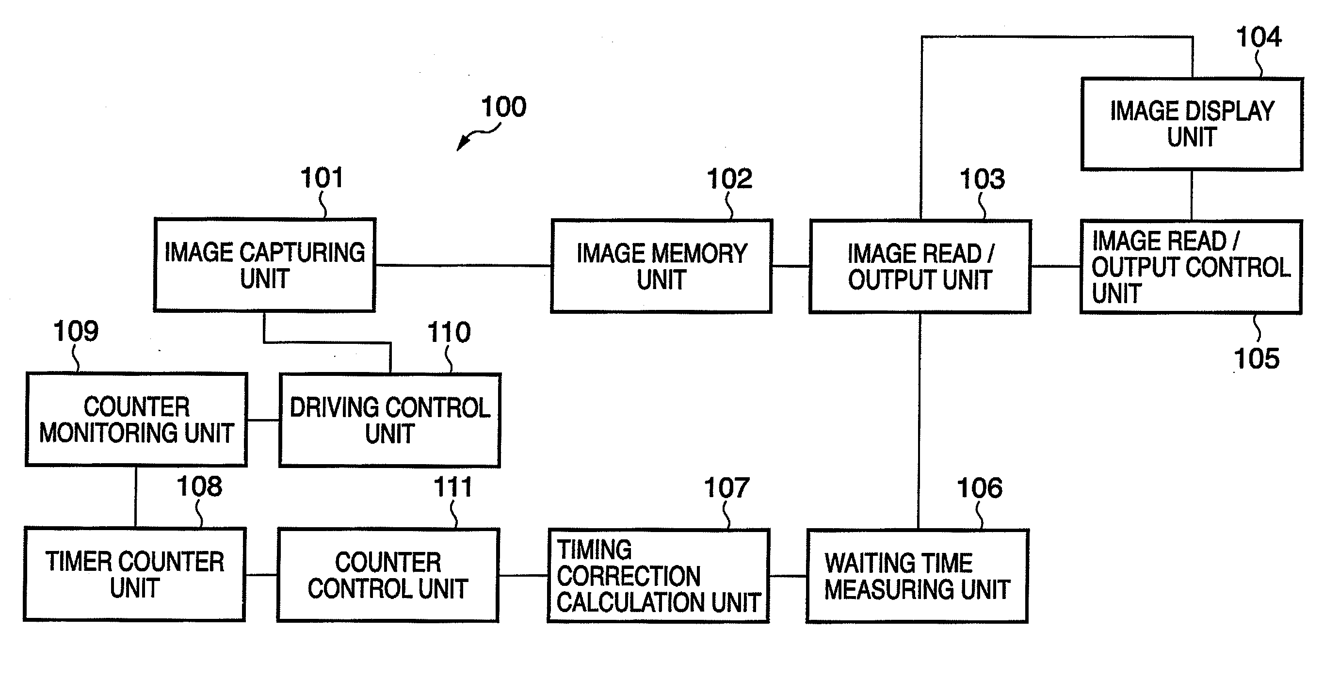
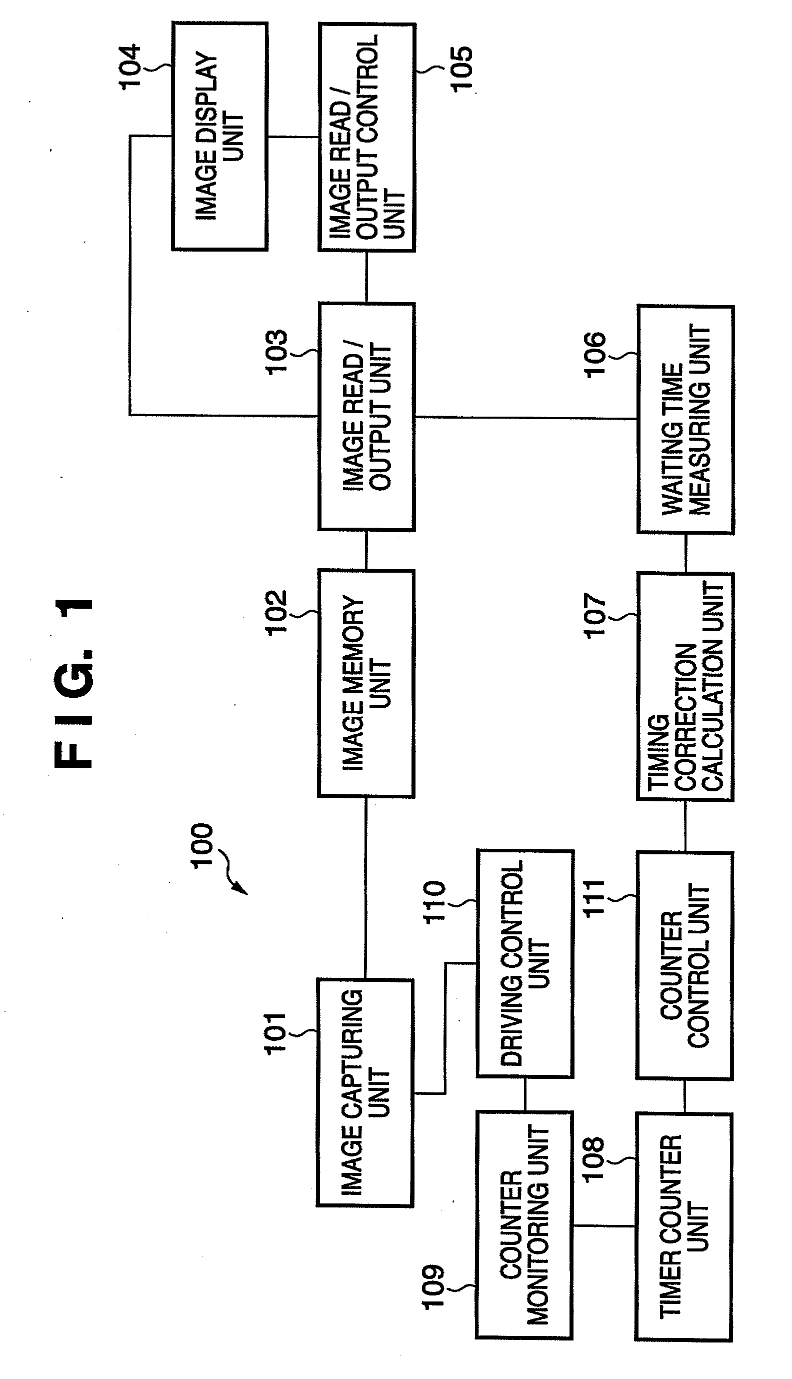
[0045]First, the configuration and the operation of an image capture and display apparatus according to a first embodiment is described. FIG. 1 is a block diagram showing the functional configuration of an image capture and display apparatus 100 according to the first embodiment.

[0046]An image capturing unit 101 obtains image data by detecting incident light or radiation (x-ray) from the outside using a photodiode and capturing that image. Note that the configuration of the image capturing unit 101 is not limited to the above. For example, the image capturing unit 101 may comprise a detector having a conversion material that directly converts X-ray into an electrical charge, such as amorphous selenium (a-Se). An image memory unit 102 temporarily stores the image data that have been obtained by the image capturing unit 101. An image read / output unit 103 reads the image data stored on the image memory unit 102 and outputs the image data for display to an image display unit 104. The im...

second embodiment

[0060]Next, the configuration and the operation of an image capture and display apparatus according to a second embodiment are described. FIG. 5 is a block diagram that shows the functional configuration of an image capture and display apparatus 500 according to the second embodiment. In FIG. 5, structural elements that are identical to those in the first embodiment (FIG. 1) have been assigned the same reference numerals as before. In the configuration of the second embodiment, a waiting time measuring unit 506 has the function of measuring the vertical synchronizing interval of the image display unit 104. A timing correction calculation unit 507, as will be described in further detail below, calculates correction data so as to perform timing correcting that exploits the vertical synchronizing interval. A parameter storage unit 512 stores the shortest interval between imaging by the image capturing unit 101.

[0061]FIGS. 6A and 6B are diagrams that illustrate the timing correction in ...

third embodiment

[0066]Next, a third embodiment is described. In the first and second embodiments, the display delay time was shortened by changing the timing at which the image capturing unit 101 begins image capture. The third embodiment describes a configuration that achieves a reduction in the display delay time by changing the nature of the processing by the image capturing unit in order to change the image capture processing time.

[0067]FIG. 7 is a block diagram that shows the functional configuration of an image capture and display apparatus 700 according to the third embodiment. In the structural layout of the third embodiment, the counter control unit 111 of the first and second embodiments is not necessary. In the third embodiment, an image capturing unit 701 has a function that allows it to change the nature of the image capture processing with a command from a driving control unit 710. The image capturing unit 701 is designed so as to allow switching between executing / omitting image proce...


PUM


Abstract

The invention provides an image capture and display control apparatus that includes an imaging control unit that operates an image capturing unit at a first time interval so as to obtain a captured image with the image capturing unit and a display control unit that displays the captured image on a display unit, which operates at a second time interval. The apparatus changes at least one of an image capture start timing of the image capturing unit and a processing time from the start of image capturing by the image capturing unit until entering a standby state in which the captured image can be displayed by the display unit, so as to shorten a display delay time, which is caused by the second time interval, from the start of operation by the image capturing unit until display of the image data by the display unit.

Description

BACKGROUND OF THE INVENTION[0001]1. Field of the Invention[0002]The present invention relates to an image capture and display control apparatus, an image capture and display control method, and an image capture and display system, for real time display on a display apparatus of images that have been captured by an image capturing apparatus.[0003]2. Description of the Related Art[0004]Image capture and display control apparatuses that are provided with an image capturing apparatus and a display apparatus, and that display captured images from the image capturing apparatus on the display apparatus in real time, are known (Japanese Patent Laid-Open No. S61-269582, Japanese Patent Laid-Open No. H5-35195, Japanese Patent Laid-Open No. 2004-325821). In apparatuses that perform the capture and display of images in real time, images are captured at a timing that is in accord with the frame rate of the image capturing apparatus, and images that are obtained are immediately displayed on the d...

Claims


Application Information

Patent Timeline
Patent Type & Authority Applications(United States)
IPC IPC(8): H04N5/228A61B6/00H04N5/232H04N5/32H04N5/335H04N5/353H04N7/18
CPCH04N5/23293H04N23/63
Inventor SHIOZAWA, HIDETOTAKEKOSHI, KOJINISHII, YUICHI
Owner CANON KK
Why Eureka
Try Eureka