Arrangement in an Imaging System for Microtitre Wells

an imaging system and microtitre technology, applied in the field of imaging systems for samples placed in microtitre wells, can solve the problems of high resolving power, inability to use large diameter wells, and inability to use wide and shallow wells, etc., to facilitate the placement of lens groups, rapid imaging, and rapid assay

Inactive Publication Date: 2008-06-26
WALLAC
View PDF8 Cites 15 Cited by
  • Summary
  • Abstract
  • Description
  • Claims
  • Application Information

AI Technical Summary

Benefits of technology

[0017]The expression ‘objective focused to infinity and at least partly arranged inside a well’ means that the rays representing a given sample point advance as a collimated beam from the objective that is at least partly arranged inside the well. In the present invention, a bundle of the collimated beams representing the different points of the sample advances from the objective towards the lens group belonging to the imaging system. Owing to this, the distance of the lens group from the objective is not critical for obtaining an accurate image in the image detector (camera). The latter significantly facilitates the placement of the lens group and the camera relative to the objective and the sample, which enables very rapid imaging. Since the lens group and the camera are expensive components compared with an objective installed inside a well, the procedure in accordance with the invention is to place a plurality of objectives focused to infinity detachably at least partly inside the wells of a sample plate; to adapt the lens group at a distance from the objective belonging to the lens system, separately from the objective and on the same side of the well bottom as the objective; to illuminate the sample in the well; to collect the rays representing the sample by means of the objective; and to form an image of the sample from the light rays describing the structure of the sample and passing through the objective, by means of the lens group to the image detector.
[0018]According to a preferred embodiment of the invention, the lens group and the camera are displaced relative to the objectives and the samples (or the objectives and samples are displaced relative to the lens group/camera combination) in such a manner that one or a few lens group/camera combinations (lens group/camera assembly) images all samples in the microtitre wells. Displacement devices are arranged to displace the lens group/camera combination at least laterally (on the horizontal plane). Each well does not have to be provided with an objective, instead, an objective array can be built and displaced from one well array of the microtitre plate to another a sufficient number of times in order to enable the processing of all wells to be assayed. In accordance therewith, by displacing for instance two objective arrays composed of four objectives 12 times, all wells of a microtitre plate...

Problems solved by technology

However, in many assays, the use of wide and shallow wells is out of the question.
Similarly, when the cells or other samples are to concentrate within a small area, wells having a large diameter cannot be used.
Increasing the diameter of the front lens of the lens system in the latter assays does not result in a higher resolving power, or in a good light collection efficiency and the desired result, since the well edges limit the usable diameter of the front lens when the front lens is close to the sample.
Placing the front lens farther away from the sample enables the utilization of the size of a large front lens in practi...

Method used


Image

  • Arrangement in an Imaging System for Microtitre Wells
  • Arrangement in an Imaging System for Microtitre Wells
  • Arrangement in an Imaging System for Microtitre Wells

Examples


second embodiment

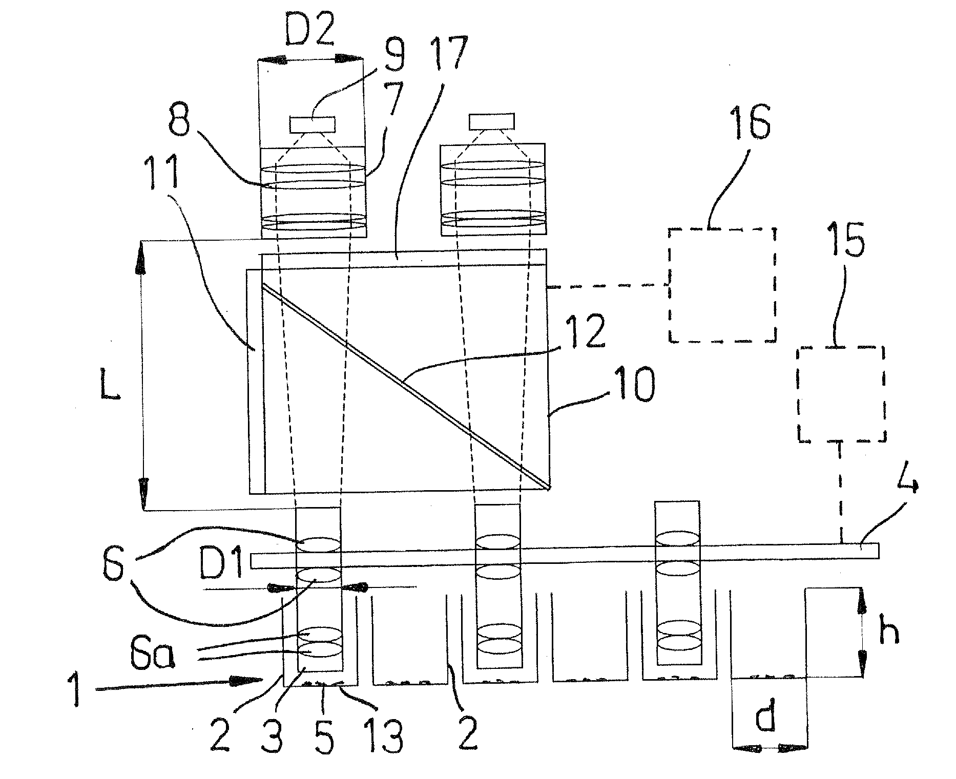
[0046]FIG. 2 shows the arrangement according to the invention. In FIG. 2, the same reference numbers are used as in FIG. 1 for corresponding components.

[0047]The arrangement of FIG. 2 differs from the embodiment of FIG. 1 in that a separate objective 3′ is installed in each well 2′, and only one lens group / camera combination 7′, 9′ is arranged to image the samples in the wells. The objectives 3′ rest on the holder 4′. A horizontal arrow 20′ indicates excitation light and an upwards-directed double arrow 21′ indicates emission light.

third embodiment

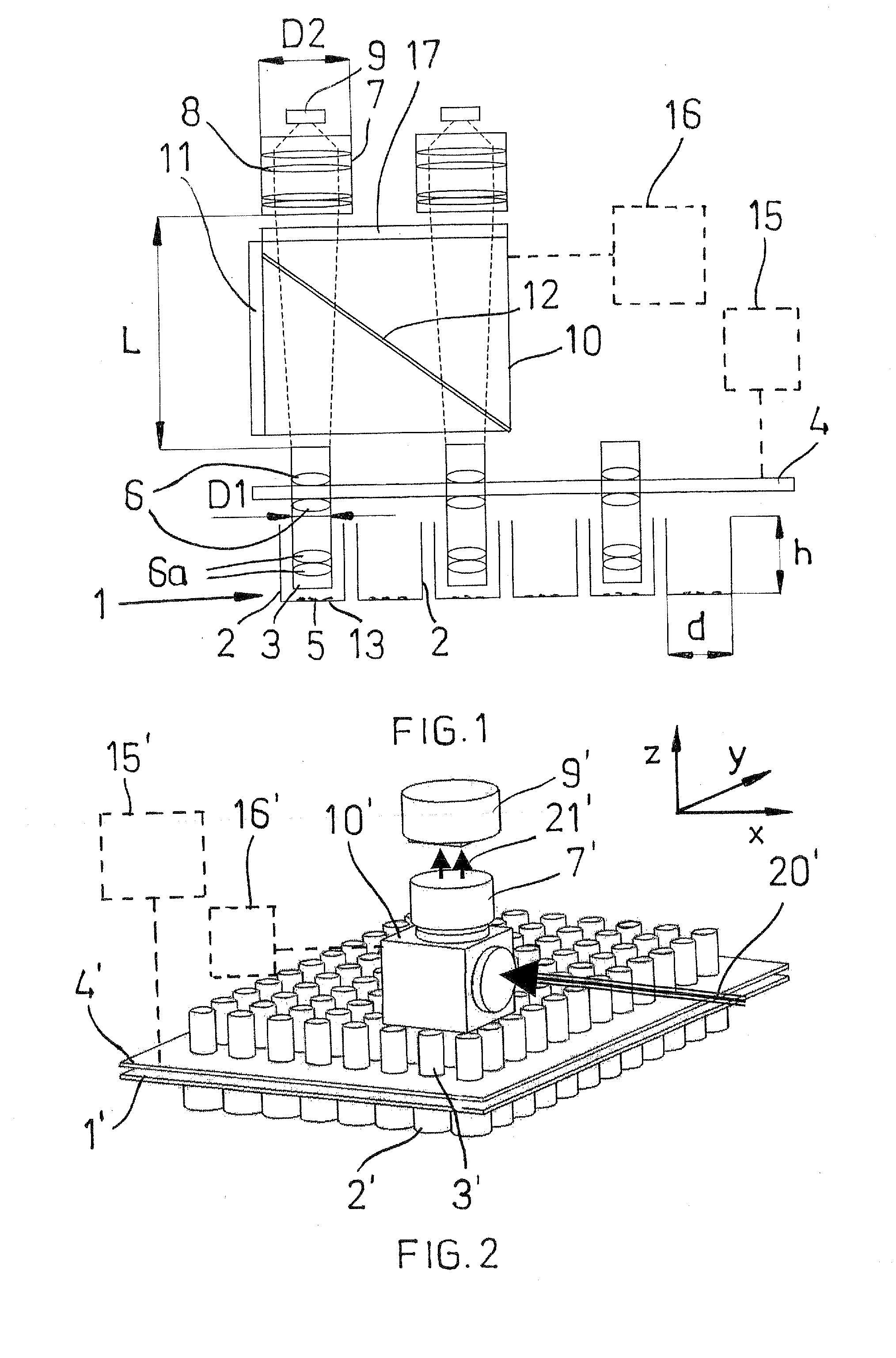
[0048]FIG. 3 shows the arrangement according to the invention. In FIG. 3, the same reference numbers are used as in FIG. 1 for corresponding components. The arrangement of FIG. 3 differs from the embodiment of FIG. 2 in that three lens group / camera combinations 7″, 9″ are arranged to image the samples. Compared with the arrangement of FIG. 2, an about threefold speed is achieved in sample imaging. The arrangement of FIG. 3 is considerably more expensive than the arrangement of FIG. 2, since it comprises two more lens group / camera combinations 7″, 9″.

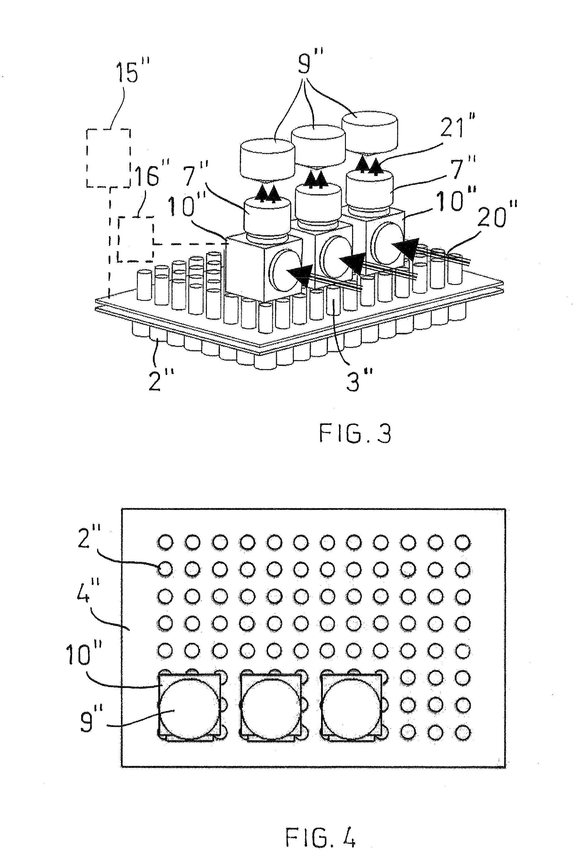
[0049]FIG. 4 is an illustrative top view of the arrangement of FIG. 3. Each lens group is arranged to receive light rays from one objective only. The diameter of the lens group is significantly larger than the diameter of the light beam emitted from the objective, owing to which there is no need to align the lens group on the x-y plane such that its optical axis is exactly in line with the optical axis of the objective, in order for the ...

fourth embodiment

[0050]FIG. 5 shows the arrangement according to the invention. In FIG. 5, the same reference numerals are used as in FIG. 1 for corresponding components.

[0051]In FIG. 5, the objective 3′″ is composed of usual lenses 6′″ arranged above a well 2′″ and a gradient index lens (GRIN lens) 6a′″ arranged inside the well. A thick broken line 20′″ depicts the passage of excitation light (from left to right). A dotted line 21′″ depicts a common light path of the excitation light and the emission light, and a thin broken line 22′″ depicts the light path of the emission light (from down upwards).


PUM


Abstract

The disclosure relates to an arrangement in an imaging system for microtitre wells, the arrangement comprising a sample plate having a plurality of wells for samples, and a lens system arranged in connection with the sample plate and comprising an objective and at least one lens group for imaging the rays representing the structure of the samples and passing through the objective to an image detector. In order for the arrangement to enable a rapid imaging of the samples in the wells with a high resolving power, the lens system comprises a plurality of objectives focused to infinity for collecting rays representing the samples, the objectives being at least partly arranged detachably inside wells in the sample plate. The disclosure also relates to a method of imaging samples in microtitre wells.

Description

BACKGROUND OF THE INVENTION[0001]The invention relates to the imaging of microtitre wells. More specifically, the invention relates to an arrangement in an imaging system for samples placed in microtitre wells, the arrangement comprising a sample plate having a plurality of wells for samples, and a lens system arranged in connection with the sample plate and comprising an objective and at least one lens group for forming an image of the structure of a sample from light rays representing the sample and passing through the objective onto an image detector.[0002]The invention also relates to a method of imaging samples placed in microtitre wells with an arrangement comprising a sample plate having a plurality of wells for samples, and a lens system arranged in connection with the sample plate and comprising an objective and at least one lens group for forming an image of the structure of a sample from light rays representing the sample and passing through the objective onto an image de...

Claims


Application Information

Patent Timeline
IPC IPC(8): G02B13/22G01N21/25G01N35/02G03B37/00
CPCG01N21/253G03B37/005G01N35/028
Inventor ERKKILA, VESAKUUSISTO, ARI
Owner WALLAC
Why Eureka
Try Eureka