Fuel cell
- Summary
- Abstract
- Description
- Claims
- Application Information
AI Technical Summary
Benefits of technology
Problems solved by technology
Method used
Image
Examples
example 1
[0103]In Example 1, a description will be made of a fuel cell to which the present invention is applied.
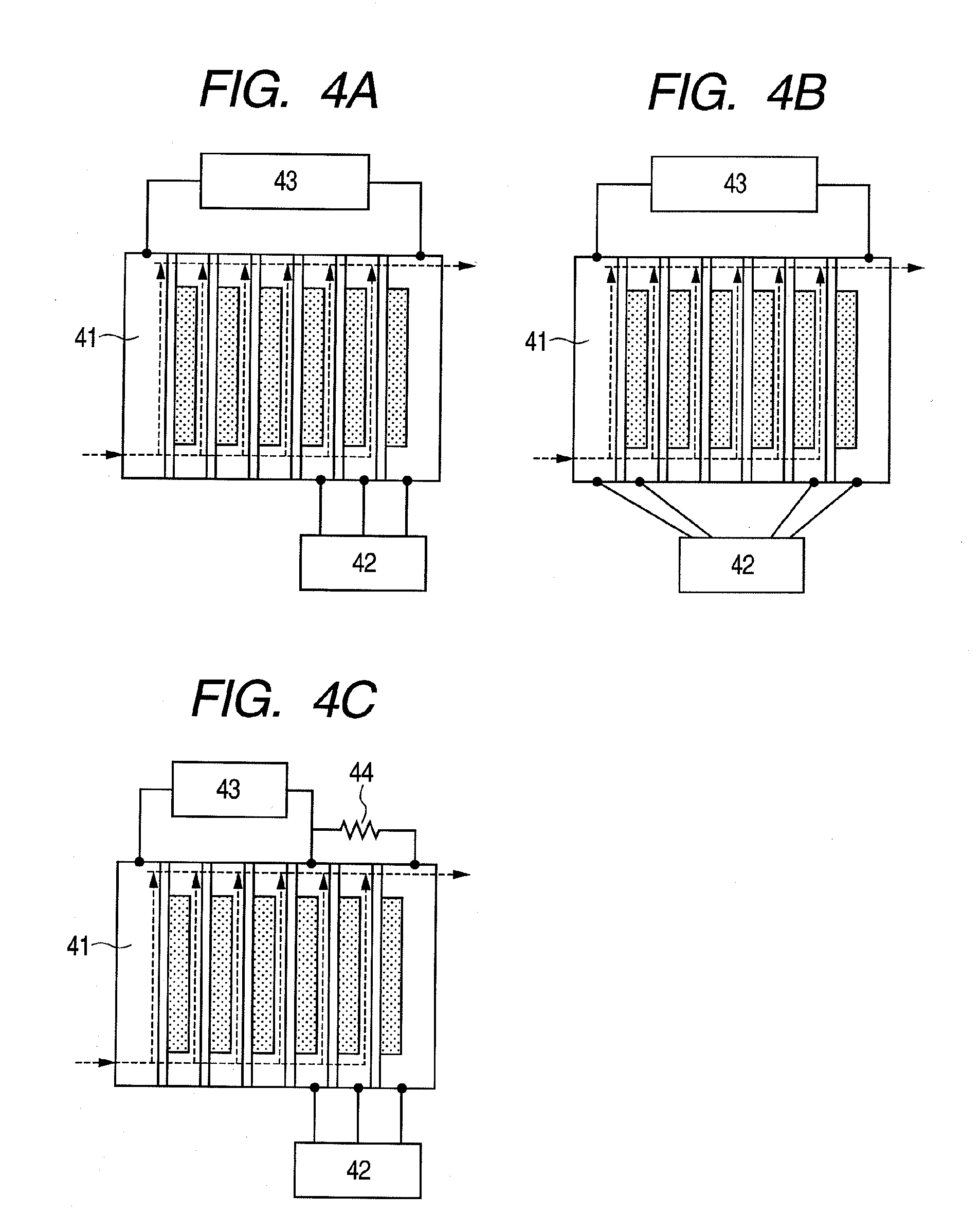
[0104]FIGS. 4A to 4C are arrangement examples of the pair of wet state detection cell units and the power generation cell units in the fuel cell stack according to this example.
[0105]In FIGS. 4A to 4C, there are illustrated a fuel cell stack 41, a control device 42, and an external load 43.
[0106]Further, arrows of each of FIGS. 4A to 4C indicate flows of the fuel in a section taken along the line A-A′ of FIG. 2.
[0107]In this example, the fuel cell includes the fuel cell stack 41, the control device 42, and the external load 43.
[0108]In this case, the control device 42 is connected to the pair of wet state detection cell units.
[0109]The pair of wet state detection cell units may be formed in any position in the fuel cell stack.
[0110]That is, the pair of wet state detection cell units may be arranged so as to be adjacent to each other as illustrated in FIG. 4A.
[0111]Alternatively, t...
example 2
[0125]In Example 2, a description will be made of a structural example in which the pair of wet state detection cell units are arranged so as to be adjacent to each other and anode electrodes (electrodes in fuel electrodes) of the power generation cell units or cathode electrodes (electrodes in oxidizer electrodes) of the power generation cell units are connected electrically in common with each other. FIGS. 6A to 6D are views for illustrating structural examples of this example. FIGS. 6A and 6C are examples in which the anode electrodes (electrodes in fuel electrodes) are commonly provided.
[0126]Further, FIGS. 6B and 6D are examples in which the cathode electrodes (electrodes in oxidizer electrodes) are commonly provided.
[0127]In FIGS. 6A to 6D, there are illustrated a fuel cell stack 61, a control device 62, and an external load 63.
[0128]By establishing the connection as illustrated in the structural example according to this example described above, the determination on the wet s...
example 3
[0151]In Example 3 of the present invention, a description will be made of detected values of the voltage in the control device and a control method for the humidifier.
[0152]FIG. 8 illustrates a time change of the detected values of the voltage in the control device during operation of the fuel cell apparatus, for illustrating this example. A polarity of the voltage is illustrated in FIG. 6C.
[0153]That is, a direction of the output voltage of the dry state detection cell unit connected to the load 65 is a positive direction.
[0154]For example, in regions A of FIG. 8, the output voltage of the dry state detection cell unit is higher than an output voltage of the excessively humidified state detection cell unit, so the fuel cell stack is determined to be excessively humidified, and the humidification of the oxidizer in the humidifier is not performed.
[0155]On the other hand, in regions B, humidification of the fuel cell stack is determined to be insufficient, so the humidification of t...
PUM
 Abstract
Description
Claims
Application Information
 - R&D
- Intellectual Property
- Life Sciences
- Materials
- Tech Scout
- Unparalleled Data Quality
- Higher Quality Content
- 60% Fewer Hallucinations
Browse by: Latest US Patents, China's latest patents, Technical Efficacy Thesaurus, Application Domain, Technology Topic, Popular Technical Reports.
© 2025 PatSnap. All rights reserved.Legal|Privacy policy|Modern Slavery Act Transparency Statement|Sitemap|About US| Contact US: help@patsnap.com


