
Method for defining military refuel orbit

a technology for defining the orbit of refueling, applied in the field of military aircraft flight management systems, can solve the problems of not using the same commercial fms capability in the prior art method, unable to recognize the complexity involved in changing the existing flight management system, and incurred significant cost to gain the capability that already exists in the commercial aircraft flight management system, etc., to achieve the effect of avoiding duplication of system capabilities, facilitating production, and facilitating production

Inactive Publication Date: 2008-06-26
HONEYWELL INT INC
View PDF23 Cites 6 Cited by
  • Summary
  • Abstract
  • Description
  • Claims
  • Application Information

AI Technical Summary

Benefits of technology

[0013]The primary advantage of the present invention is that it produces military aircraft flight management systems rapidly and inexpensively with performance equivalent to existing commercial capabilities.
[0014]Another advantage of the invention is that it is easier to make since all changes are made in the much less complex Tactical FMS.
[0015]A further advantage of the invention is that it is safer since the existing, certified commercial flight management system does not require any changes.
[0016]Yet another advantage of the present invention is that it avoids the duplication of system capabilities common between the commercial and military flight management systems.

Problems solved by technology

The problem manifests itself when a military aircraft flight management system must either be changed or created to contain the same capability that already exists within existing commercial aircraft flight management system capability.
Since the military aircraft flight management system must be changed, significant cost is incurred to gain capability that already exists in the commercial aircraft flight management system.
These attempted prior art solutions have failed to recognize the complexity involved in changing existing flight management systems.
None of the prior art methods use an unchanged commercial FMS capability to be used with no changes to fly military refueling orbits.

Method used


Image

  • Method for defining military refuel orbit
  • Method for defining military refuel orbit

Examples


Embodiment Construction

Best Modes for Carrying Out the Invention

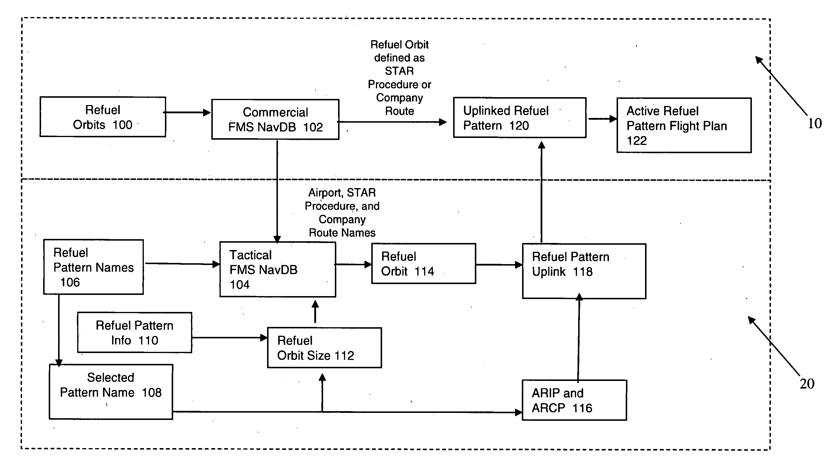
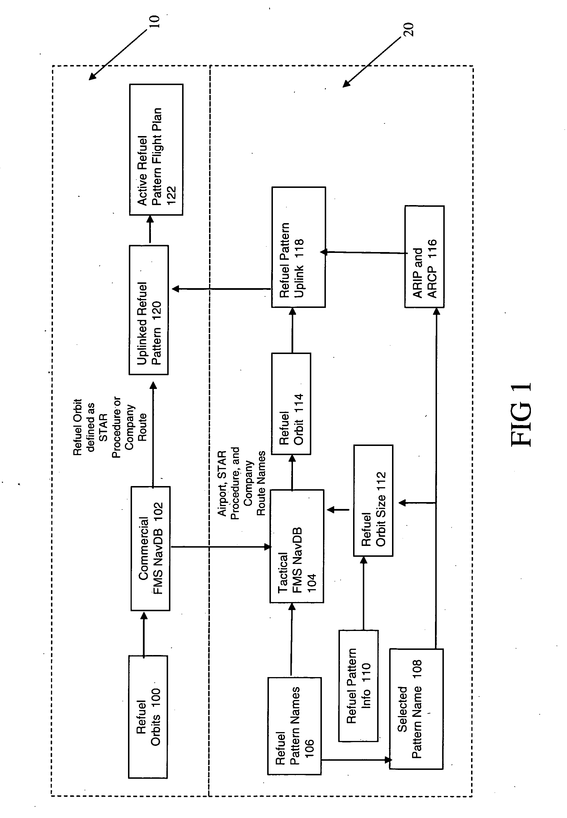
[0020]A Tactical FMS or other device used to uplink the military refuel orbit flight plan is developed as a separate avionics box or partition if installed in an Integrated Modular Avionics (IMA) architecture. Refuel orbits defined to cover all combinations of refuel orbit sizes needed for a particular military aircraft are stored in a commercial FMS NavDB. The aircraft flight crew specifies the information to define the desired refuel orbit (e.g., refuel orbit name), the true airspeed (TAS), and the ARIP to ARCP drift the orbit will be flown with in the Tactical FMS using (M)CDU pages with a similar human factors interface to those in the existing commercial FMS. The Tactical FMS uses the flight crew entered information to determine the refuel orbit size, ARIP, and ARCP, then uplinks the defined refuel orbit and associated ARIP and ARCP using the commercial FMS's existing datalink interface.

[0021]The preferred method of the invention is show...


PUM


Abstract

Defining military refuel orbit using unchanged commercial aircraft FMS capability includes uplinking military refuel orbits using an existing commercial FMS datalink function. Refuel orbits are defined as commercial NavDB STAR procedures using RF and TF legs. STAR procedures can also be stored within company routes. Company route names and STAR procedures are stored within a NavDB used in a military unique system. The military system creates a flight plan with custom, place / bearing / distance, place bearing place bearing, or latitude / longitude waypoints to define the military refuel pattern ARIP and ARCP. This is combined with the refuel orbit stored in the military NavDB as a STAR procedure or company route name to define a refuel pattern flight plan. The military system uplinks the flight plan using the existing commercial FMS datalink function. The FMS extracts the appropriate refuel orbit from the commercial FMS NavDB using the uplinked STAR procedure or company route name.

Description

BACKGROUND OF THE INVENTION[0001]1. Field of the Invention (Technical Field)[0002]The present invention relates to military aircraft Flight Management Systems (FMS) and more particularly to a method for defining military refuel orbit using an unchanged commercial aircraft FMS capability.[0003]2. Background Art[0004]Refuel orbits are defined as Standard Terminal Arrival Route (STAR) procedures using constant radius to a fix (RF) and track to a fix (TF) flight legs in a commercial FMS navigation database (NavDB). The STAR procedures can also be stored within company routes in the commercial NavDB company route file. Storing these refuel orbits in the commercial FMS NavDB is the equivalent of a custom commercial NavDB for a military customer. The names of the company route and / or STAR procedures defining the refuel orbits are also stored in a NavDB of a military unique system (i.e., a Tactical FMS) developed solely for the military aircraft. The Tactical FMS is used to define a commerc...

Claims


Application Information

Patent Timeline
Patent Type & Authority Applications(United States)
IPC IPC(8): G01C23/00
CPCG01C23/00B64D39/00
Inventor CARLTON, ROBERT S.
Owner HONEYWELL INT INC
Learn More