Fast algorithm for peer-to-peer shortest path problem

a peer-to-peer shortest path and algorithm technology, applied in the field of pathsearch technology, can solve the problems of becoming unrealistic in terms of calculation amount and conventionally being a problem, and achieve the effect of speeding up the path search

Inactive Publication Date: 2008-06-26
IBM CORP
View PDF4 Cites 17 Cited by
  • Summary
  • Abstract
  • Description
  • Claims
  • Application Information

AI Technical Summary

Benefits of technology

[0021]To cope with these problems, an object of the present invention is to provide a technique used for speeding up a path search.

Problems solved by technology

This algorithm is guaranteed to always have a solution, but becomes unrealistic in terms of calculation amount when the number of vertices in the graph G is increased.
Here, a part (a method of calculating the upper and lower limits of d(v,w)), which is a black box in the abovementioned A* search algorithm, has conventionally been a problem.

Method used


Image

  • Fast algorithm for peer-to-peer shortest path problem
  • Fast algorithm for peer-to-peer shortest path problem
  • Fast algorithm for peer-to-peer shortest path problem

Examples


Embodiment Construction

[0041]An embodiment example of the present invention will be described below based on the drawings. Unless otherwise stated, the same reference numerals refer to the same subjects throughout all of the drawings. Note that described below is one embodiment of the present invention, and that there is no intention to limit the present invention to the contents described in connection with this embodiment example.

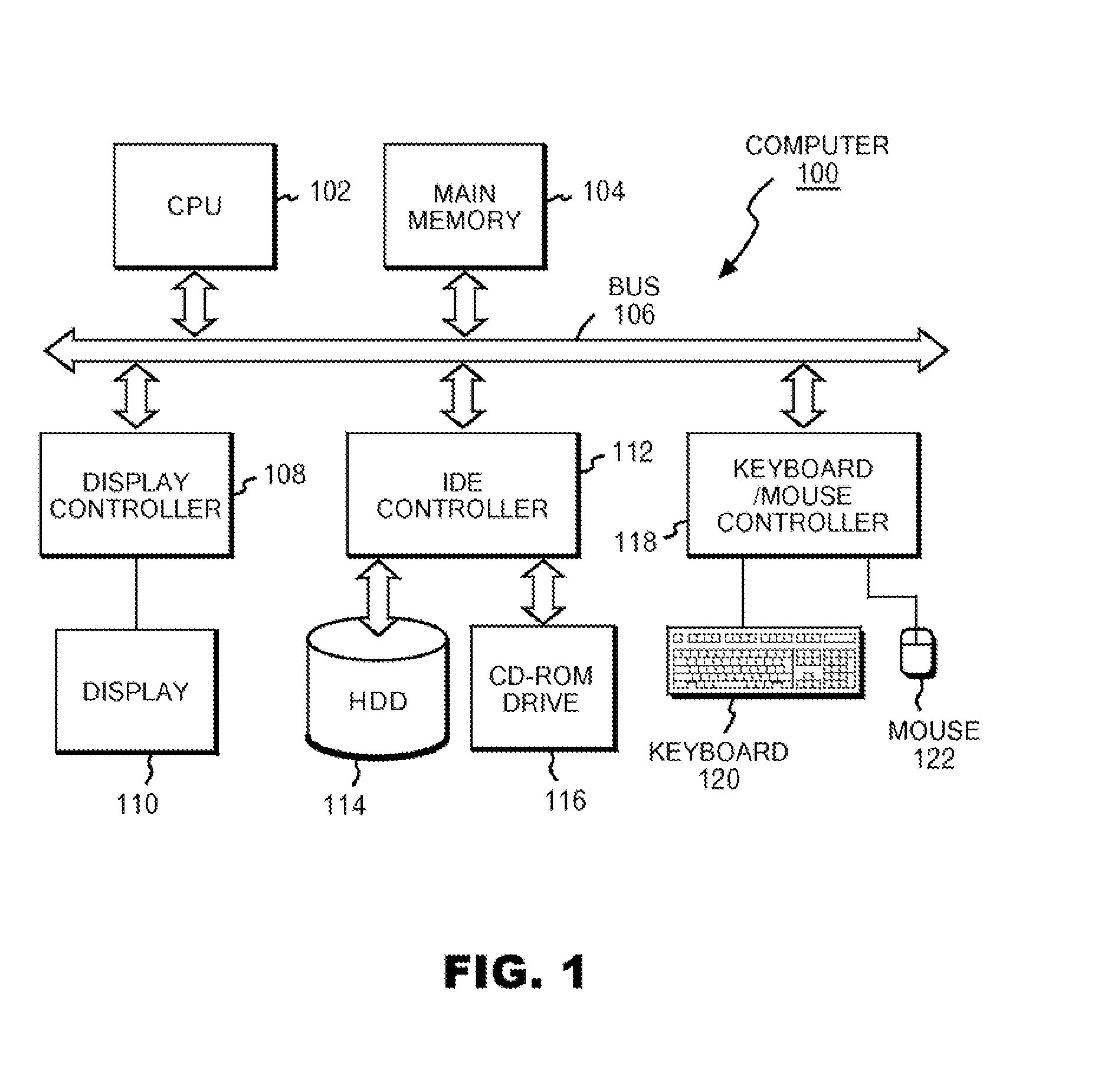
[0042]FIG. 1 is a block diagram of a hardware configuration used for executing a method of the present invention. In FIG. 1, a computer 100 includes a CPU 102 and a main memory 104, and these are connected to a bus 106. The main memory 104 is one having a storage capacity of at least 512 MB, and suitably not less than 1 GB. In order to load, onto the main memory, data (all-vertices data) on all of vertices in a later described graph, the larger the capacity of the main memory 104 is, the more preferable. The CPU is, suitably, one based on an architecture of 32 bits or 64 bits, ...


PUM


Abstract

A plurality of landmarks selected from a source weighed graph on which a path search is performed; and the shortest path lengths between landmarks, and the shortest path lengths from vertices to landmarks adjacent to the respective vertices are calculated, and are stored in a memory device so as to be later referable. Routines for calculating upper and lower limits of the shortest path length corresponding to two vertices v and w are prepared by using expressions derived from quadrangle inequalities formed of the two vertices v and w as well as two landmarks adjacent to the respective vertices v and w. In response to a call from an A* search program, these routines return the upper limit or the lower limit of the shortest path length corresponding to v and w by referring to the shortest path lengths between landmarks, and the shortest path lengths from vertices to landmarks adjacent to the respective vertices, which have been previously stored in the memory device.

Description

CROSS-REFERENCE TO RELATED APPLICATIONS[0001]This application claims priority under 35 U.S.C. § 119 to Japanese Patent Application No. 2006-345224 filed Dec. 22, 2006, the entire text of which is specifically incorporated by reference herein.BACKGROUND OF THE INVENTION[0002]1. Field of the Invention[0003]The present invention relates to a path-search technology. More specifically, the present invention relates to a method of, a program for, and a system for speeding up a path search.[0004]2. Description of the Related Art[0005]In recent years, as the number of optimum traffic route-search services in car navigation systems and websites has increased, there has been a growing demand for a speeded-up technique for finding a route by use of a computer. In terms of computer science, this comes down to an algorithm of determining the shortest path in a weighted graph.[0006]Incidentally, as a classic technique for an algorithm of determining the shortest path in a weighted graph, there ha...

Claims


Application Information

Patent Timeline
Patent Type & Authority Applications(United States)
IPC IPC(8): G06F15/16
CPCH04L45/12H04L45/00
Inventor IMAMURA, TOMOKAZUYANAGISAWA, HIROKI
Owner IBM CORP
Why Eureka
Try Eureka