Electromechanical Parking Brake

Inactive Publication Date: 2008-07-03
MAG EH
View PDF11 Cites 5 Cited by
  • Summary
  • Abstract
  • Description
  • Claims
  • Application Information

AI Technical Summary

Benefits of technology

[0007]It is thus one of the objects of the present invention to provide an actuator for parking brakes of vehicles that is basically simple, load sensitive, does not take up much

Problems solved by technology

The use of such low efficiency self-locking drives, however, require the use of bigger motors having higher current consumption and lower sensitivity in dete

Method used


Image

  • Electromechanical Parking Brake
  • Electromechanical Parking Brake
  • Electromechanical Parking Brake

Examples


Embodiment Construction

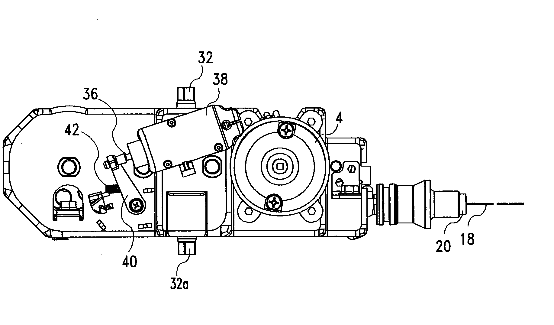
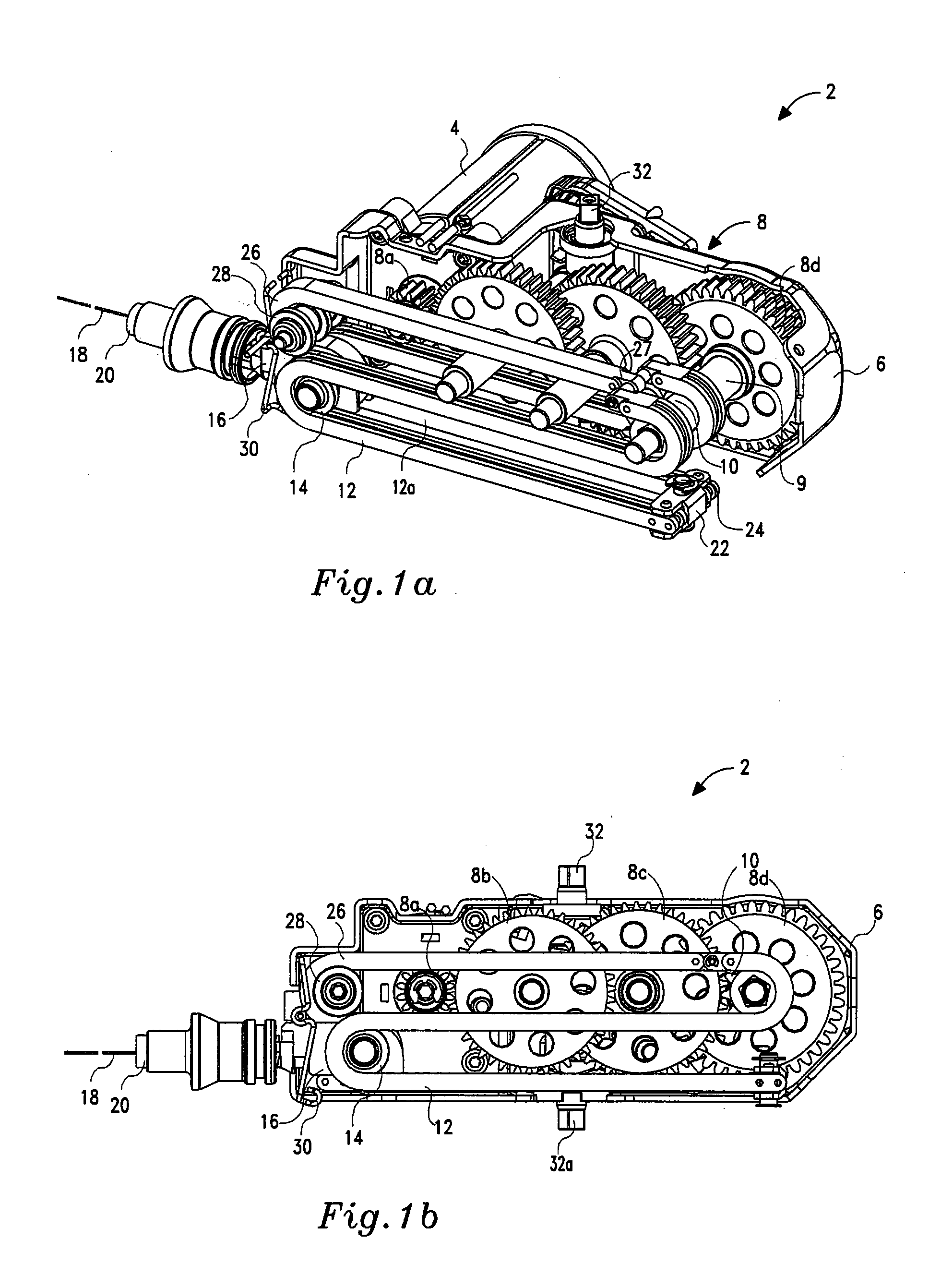
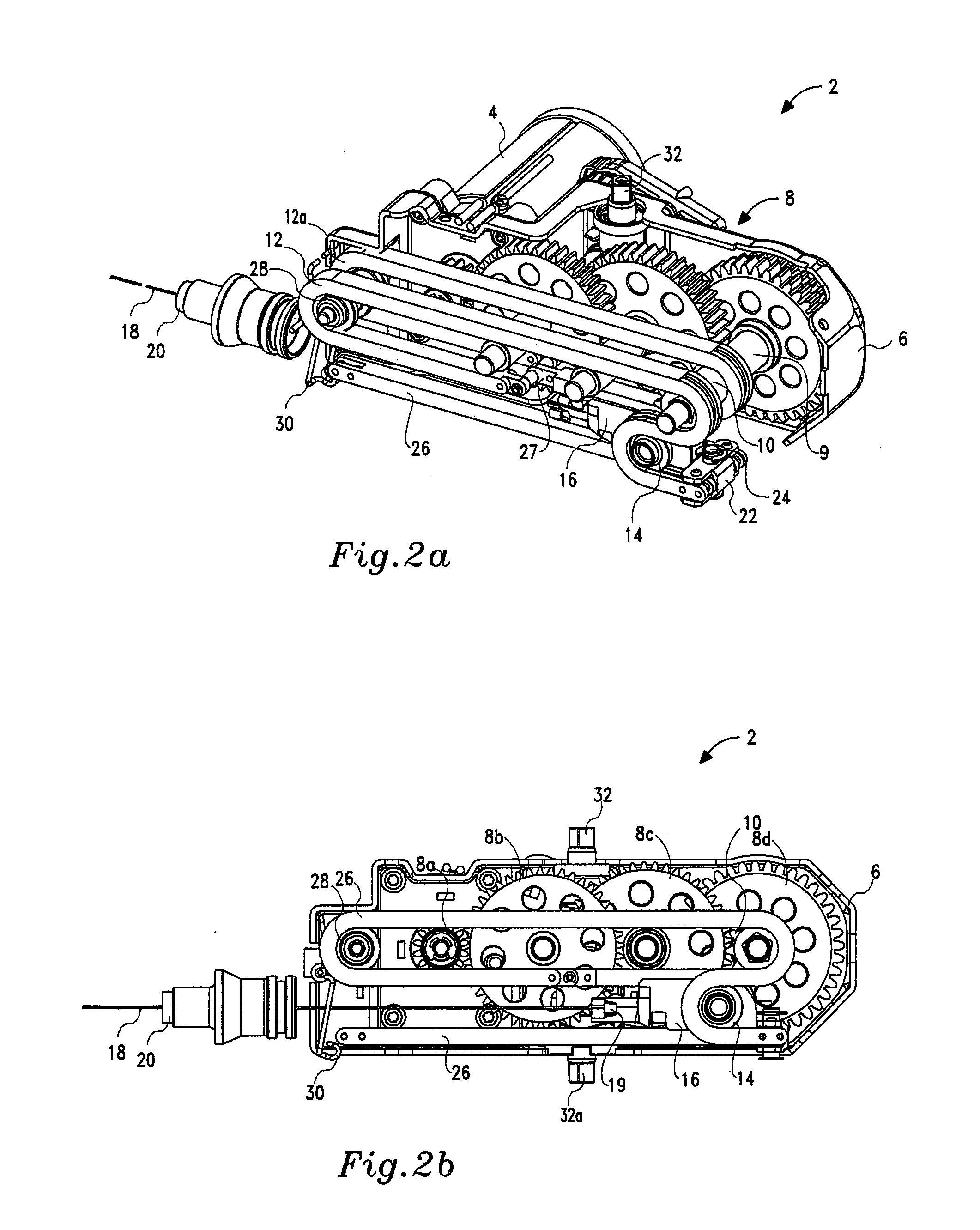
[0016]Referring now to a preferred embodiment according to the invention, there are seen schematic perspective and front views, respectively, of the subassembly, generally referenced 2, in a released state (FIGS. 1a and 1b), and in an activated state (FIGS. 2a and 2b).

[0017]A reversible electric motor 4 mounted on bracket 6 is coupled to a three-stage reduction gear train generally referenced 8. The reduction gear train 8 comprises pinion 8a mounted on a rotor shaft of motor 4, first gear 8b, second gear 8c and last gear 8d. The last gear 8d is fixedly attached to shaft 9 with integral dual sprocket 10. The reduction gear train 8, is composed of spur or helical gears, known to be non-locking, in the sense that it enables deliverance of torque from the motor 4 to the dual sprocket 10, and vice-versa.

[0018]Dual sprocket 10, is rotated as a unit with the last gear 8d and drives a pair of identical schematically shown power transmission chain (e.g., roller chain) sections 12, 12a, partl...


PUM


Abstract

There is provided an electromechanical actuator for a parking brake system of a vehicle, including an electric motor, reduction gear train associated with the motor for transmitting motion from the motor to a single power transmission chain sprocket, one power transmission chain section drivable by the sprocket partly encircling one sheave, rotatably mounted on a free longitudinally movable pulley block, an end of the power transmission chain being attached to a first stationary anchor point, and a connector connecting the pulley block to the vehicle's parking brake system.

Description

FIELD OF THE INVENTION[0001]The present invention relates to an electromechanical parking brake actuator for motor vehicles, and more particularly to a linear electromechanical push-pull actuator intended for tensioning the parking brake cable or lever and the releasing thereof.BACKGROUND OF THE INVENTION[0002]Vehicular brake mechanisms generate braking torque to the vehicle's wheels, comprising, for example, drums with friction linings or a caliper that presses friction pads against disks. The braking mechanism is designed so that application of force will cause braking torque build-up, while release of the force will remove the braking torque. In motor vehicles, the service brake system generally consists of hydraulically operated disk or drum brakes actuated by foot force, normally vacuum or pressure boosted. The parking brake is normally manually activated on a pair of front or rear wheels by means of mechanical links boosting the hand force and performing the same disk clamping...

Claims


Application Information

Patent Timeline
IPC IPC(8): B60T7/02
CPCB60T13/746
Inventor RAZ, DAN
Owner MAG EH
Why Eureka
Try Eureka