Real-time, continuous-wave terahertz imaging using a microbolometer focal-plane array

a microbolometer and focal-plane array technology, applied in the field of terahertz (thz) imaging systems, can solve the problems of limiting the image acquisition time to the mechanical scan rate of the system, requiring minutes to acquire the complete image, and adding to system complexity, so as to reduce the effect of ambient infrared radiation

Inactive Publication Date: 2008-07-03
MASSACHUSETTS INST OF TECH
View PDF13 Cites 155 Cited by
  • Summary
  • Abstract
  • Description
  • Claims
  • Application Information

AI Technical Summary

Benefits of technology

[0008]In a related aspect, the imaging system can include an imaging plane where an object to be imaged can be disposed. Further, the imaging system can acquire an image of the object in real-time at a rate of at least about 20 frames per second (e.g., 60 frames per second). The images can be used directly or accumulated to further improve image quality, e.g., by reducing noise.
[0012]In another aspect, a terahertz imaging system is disclosed that includes a source of terahertz radiation (e.g., a QCL) generating radiation pulses having one or more frequency components in a range of about 0.1 THz to about 10 THz, and an optical system for directing the radiation pulses to an object to be imaged. The system further includes an array of radiation detecting elements for detecting the THz radiation transmitted through the object (or reflected by the object) to generate detection signals. The radiation detecting elements are further adapted to generate reference signals in response to detection of unwanted ambient infrared radiation in absence of the THz radiation. The term “in the absence of THz radiation” is intended to encompass the cases in which the THz radiation (and / or its effect on the detector) is not present, or the THz radiation (and / or its effect on the detection elements) is substantially attenuated (e.g., less than about 10 percent, and preferably less than about 5 percent of the value in presence of the THz pulses). The imaging system further includes a processor that is in communication with the detection array to generate a THz image of the object based on a difference between said detection and reference signals. For example, the processor can subtract a reference signal generated by each detection element from a detection signal generated by that element to form the THz image, thus greatly reducing the effect of the ambient infrared radiation.

Problems solved by technology

However, conventional imaging systems often obtain an image of an object by linearly scanning the object through a tightly focused THz beam—a practice that limits the image acquisition time to the mechanical scan rate of the system.
With upper limits of hundreds of pixels per second for acquiring an image by mechanical scanning, in this approach, a complete image requires minutes to be acquired.
This arrangement, however, requires precise timing of optical and THz pulses, thus necessitating a scanning delay mechanism that adds to system complexity.
Moreover, such systems are inherently broad-band (typically short THz pulses (e.g., less than 1 ps) are utilized that result in a bandwidth larger that 1 THz), and hence not suitable for applications that require coherent narrow-band illuminating radiation for frequency-sensitive imaging.

Method used


Image

  • Real-time, continuous-wave terahertz imaging using a microbolometer focal-plane array
  • Real-time, continuous-wave terahertz imaging using a microbolometer focal-plane array
  • Real-time, continuous-wave terahertz imaging using a microbolometer focal-plane array

Examples


Embodiment Construction

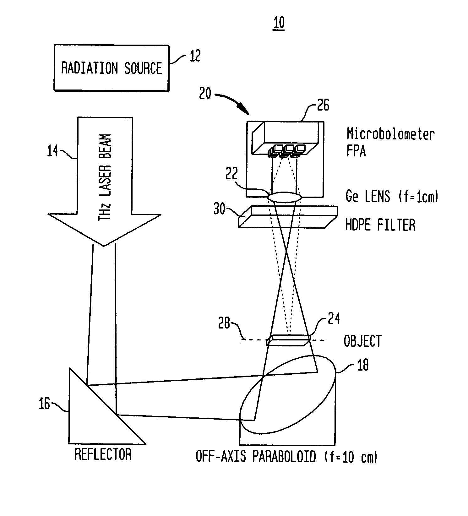
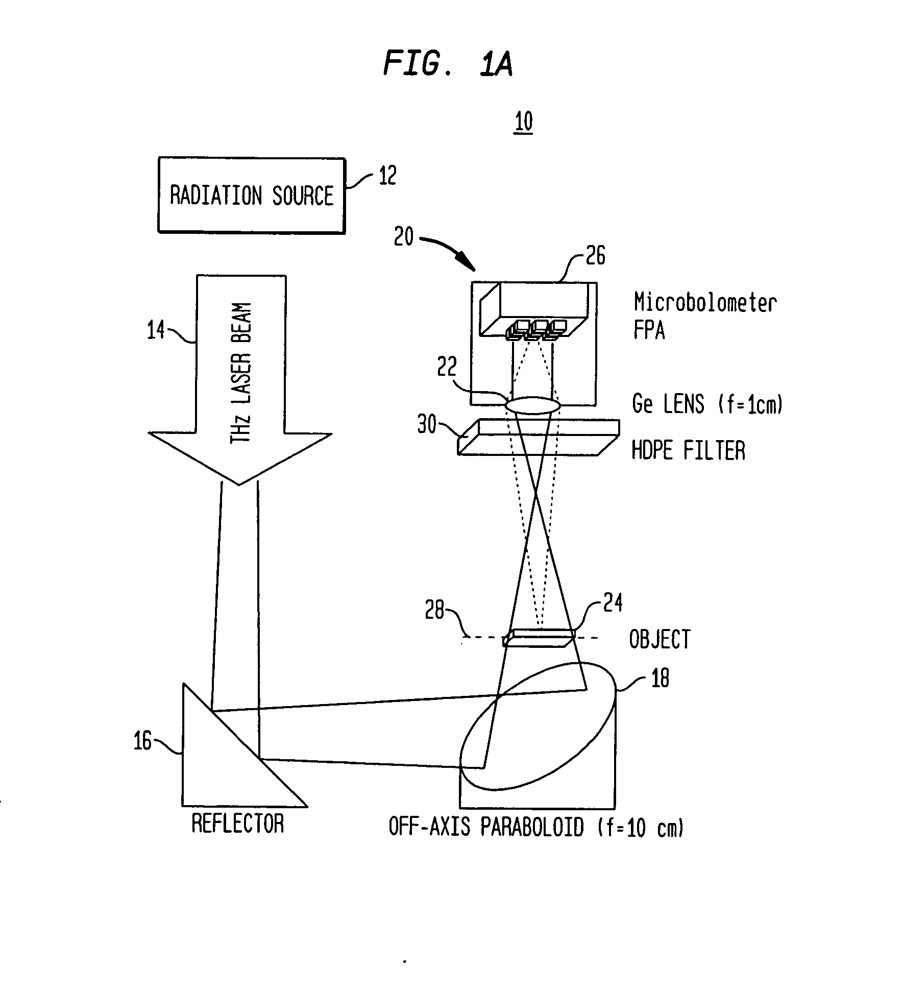
[0033]FIG. 1A schematically illustrates a terahertz imaging system 10 according to an exemplary embodiment of the invention that includes a source 12 for generating radiation having one or more frequency components in a range of about 0.1 terahertz (THz) to about 10 THz (corresponding to a wavelength range of about 30 to about 3000 microns). In many embodiments, quantum cascade lasers (QCLs) are employed for generating the terahertz radiation (e.g., continuous-wave (CW) or pulsed radiation). Some examples of quantum cascade lasers suitable for use in the practice of the present invention as terahertz radiation sources are described in co-pending applications of the assignee of the present application entitled “Terahertz Lasers and Amplifiers Based on Resonant Optical Phonon Scattering to Achieve Population Inversion” (filed on Sep. 12, 2003 and having an application Ser. No. 10 / 661,831) and “Metal Waveguides for Mode Confinement in Terahertz Lasers and Amplifiers” (filed on Sep. 12,...


PUM

PropertyMeasurementUnit
poweraaaaaaaaaa
poweraaaaaaaaaa
poweraaaaaaaaaa

Abstract

The present invention generally provides a terahertz (THz) imaging system that includes a source for generating radiation (e.g., a quantum cascade laser) having one or more frequencies in a range of about 0.1 THz to about 10 THz, and a two-dimensional detector array comprising a plurality of radiation detecting elements that are capable of detecting radiation in that frequency range. An optical system directs radiation from the source to an object to be imaged. The detector array detects at least a portion of the radiation transmitted through the object (or reflected by the object) so as to form a THz image of that object.

Description

RELATED APPLICATION[0001]The present application claims priority to a provisional application entitled “Real-time, Continuous-wave Terahertz Imaging Using a Microbolometer Focal-Plane Array,” filed on Mar. 21, 2005 and having a Ser. No. 60 / 663,902, which is herein incorporated by reference.BACKGROUND OF THE INVENTION[0002]The present invention relates generally to terahertz (THz) imaging systems, and more particularly to such imaging systems that can acquire images in real-time at video rates, e.g., by utilizing a coherent narrow-band THz illumination source.[0003]The transparency of materials to radiation having frequencies in a range of about 0.1 to about 10 terahertz (THz) can be quite different than their transparency to radiation having frequencies in the visible range. For example, germanium, silicon, polytetrafluoroethylene plastic (Teflon), high and low-density polyethylene plastics (HDPE and LDPE), teeth, leaves, clothing and envelopes typically become more transparent at t...

Claims


Application Information

Patent Timeline
Patent Type & Authority Applications(United States)
IPC IPC(8): G01N21/35
CPCG01N21/3151G01N21/3563G01N21/3581
Inventor HU, QINGMIN LEE, ALAN W.
Owner MASSACHUSETTS INST OF TECH
Why Eureka
Try Eureka