
Alternative sensingsensing circuit for MEMS microphone and sensingsensing method therefof

a sensing circuit and microphone technology, applied in the field of sensing circuit for microelectromechanical system microphones and sensing methods, can solve problems such as increasing the overall power consumption of chips

Inactive Publication Date: 2008-07-03
IND TECH RES INST
View PDF4 Cites 24 Cited by
  • Summary
  • Abstract
  • Description
  • Claims
  • Application Information

AI Technical Summary

Benefits of technology

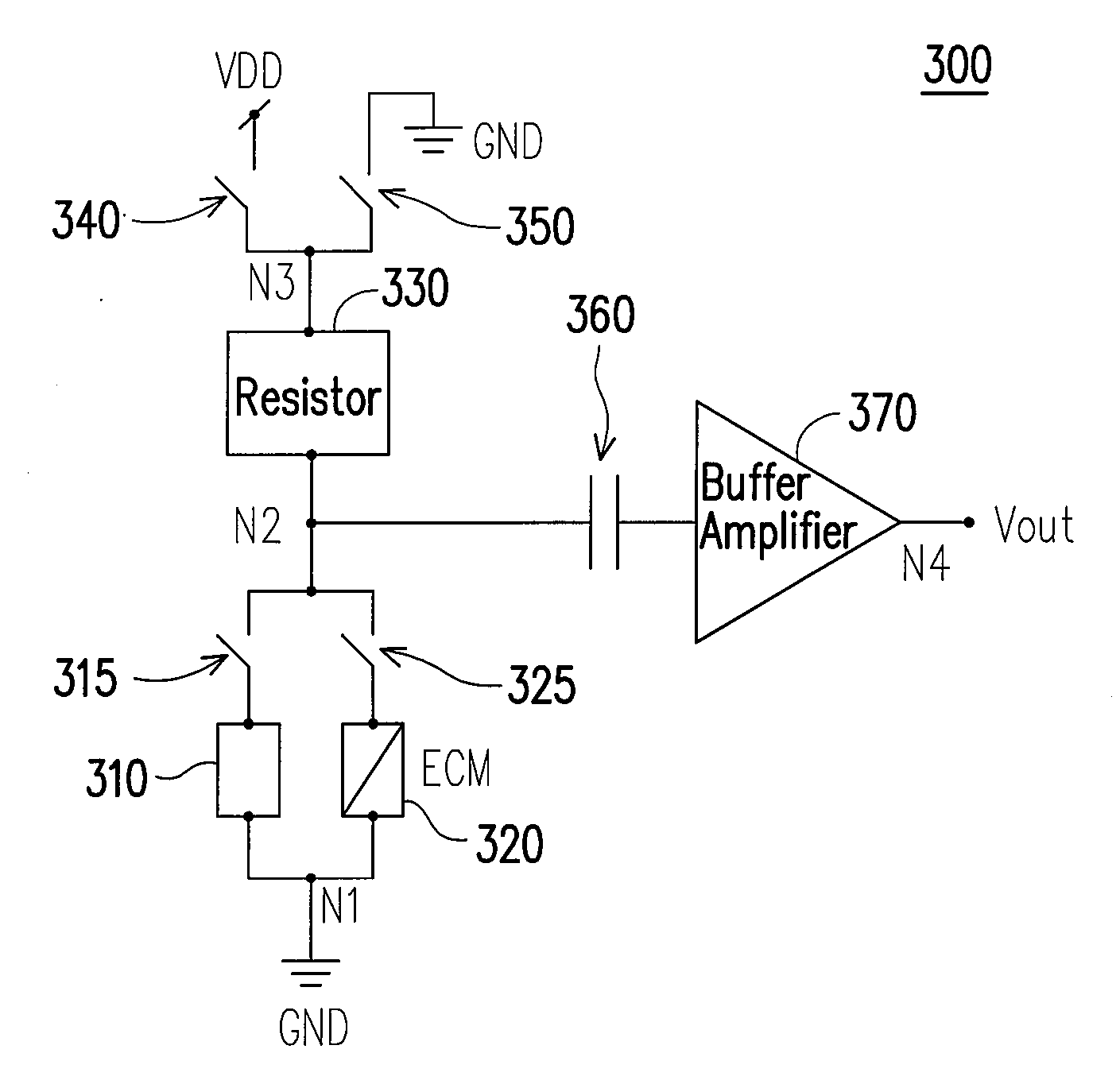
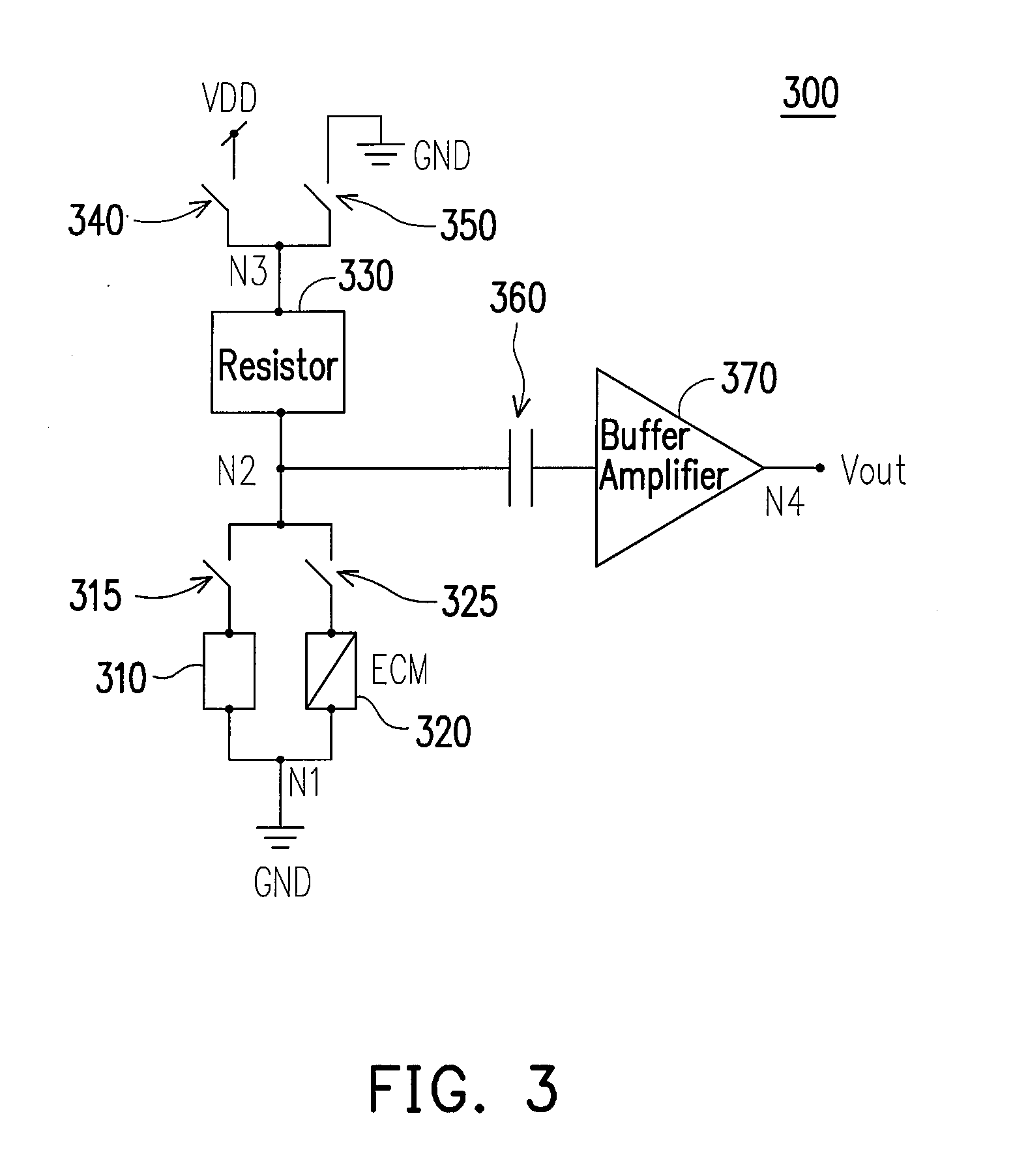
[0015]The sensing circuit for the MEMS microphone of the present invention includes an MEMS condenser microphone component, an MEMS electret condenser microphone component, first, second, third and fourth switches, and a bias resistor. The sensing circuit for the MEMS microphone of the present invention selectively forms a first current path or a second current path. When the first switch and the third switch are turned on, the first current path is formed, and the second switch and the fourth switch are turned off. The first current path allows the MEMS condenser microphone component to obtain a bias from the voltage source through the bias component, such that the MEMS condenser microphone component senses an acoustic wave signal as the output of the sensing circuit for the MEMS microphone. When the second switch and the fourth switch are turned on, the second current path is formed, and the first switch and the third switch are turned off. The second current path allows outputting the sensing result of the acoustic wave sensed by the MEMS electret condenser microphone component as the output of the sensing circuit for the MEMS microphone.

Problems solved by technology

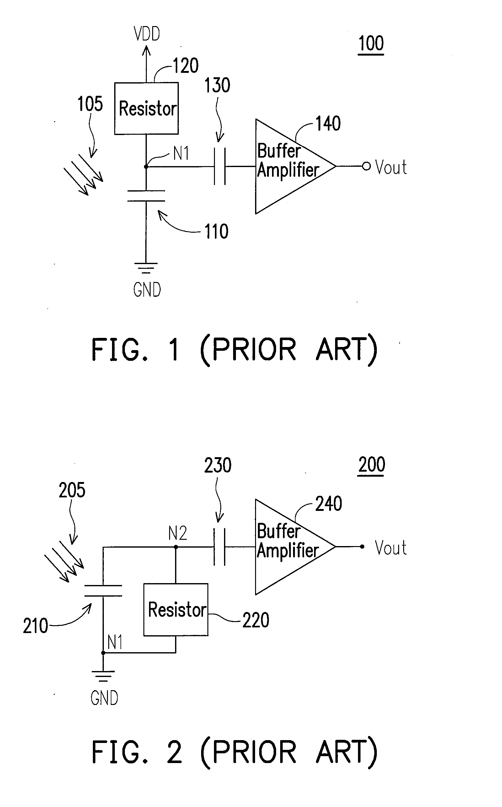
Therefore, this kind of microphone when used in a subsequent circuit will lead to the increase of the overall power consumption of the chip.

Method used


Image

  • Alternative sensingsensing circuit for MEMS microphone and sensingsensing method therefof
  • Alternative sensingsensing circuit for MEMS microphone and sensingsensing method therefof
  • Alternative sensingsensing circuit for MEMS microphone and sensingsensing method therefof

Examples


Embodiment Construction

[0026]In many application environments, the requirement for specifications is usually decided according to the objectives and appeals. For example, the microphones used in mobile apparatuses such as mobile phones are mainly required to have low power consumption. Whereas, in the field of precise signal sensing such as the hearing aids, the components with high sensitivity are usually required.

[0027]The two kinds of MEMS microphones commonly used have their own advantages and disadvantages. For example, the MEMS electret condenser microphone has the advantages of low power consumption. The MEMS condenser microphone has the advantages of high sensitivity. Due to different architectures, the circuit architectures are different. Therefore, a circuit architecture that can read both the signal of the MEMS electret condenser microphone component and the signal of the MEMS condenser microphone component is desired, so that the single component can be widely applied, and the applicability of...


PUM


Abstract

An alternative sensing circuit for a micro-electro-mechanical system (MEMS) microphone and a sensing method thereof are provided. The sensing circuit reads out output signals of an MEMS electret microphone or an MEMS condenser microphone. In considering different operating requirements of the different MEMS microphones, for example, low power consumption for the MEMS electret condenser microphone or high sensitivity for the MEMS condenser microphone, the manner of using two kinds of MEMS microphone sensing components in one circuit can significantly increase the flexibility of using the MEMS microphone and can be applied to the application or design of a condenser sensing component.

Description

CROSS-REFERENCE TO RELATED APPLICATION[0001]This application claims the priority benefit of Taiwan application serial no. 95149985, filed Dec. 29, 2006. All disclosure of the Taiwan application is incorporated herein by reference.BACKGROUND OF THE INVENTION[0002]1. Field of the Invention[0003]The present invention relates to a sensing circuit for a micro-electro-mechanical system (MEMS) microphone. More particularly, the present invention relates to an integrated alternative sensing circuit for an MEMS microphone and a sensing method thereof.[0004]2. Description of Related Art[0005]Micro-Electro-Mechanical System (MEMS) technique is a design based on microminiaturized mechanical structures, which among others, is mainly used in three fields including micro sensor, micro actuator, and micro structure components. The micro sensor can employ relative semiconductor process techniques, and thus can be integrated with integrated circuits (ICs). Therefore, the competitiveness of this techn...

Claims


Application Information

Patent Timeline
Patent Type & Authority Applications(United States)
IPC IPC(8): B81B3/00
CPCH04R1/04H04R19/005H04R3/00
Inventor HSU, YU-CHUNCHOU, WEN-CHIEH
Owner IND TECH RES INST
Learn More