Clamping jaws and clamping device for clamping workpieces

a technology of clamping device and workpiece, which is applied in the direction of metal-working holders, positioning apparatuses, supports, etc., can solve the problems of inability to clamp workpieces, rigid construction, and the need for several valves, and achieves the effect of small cross-section, easy electrical control, and cancellation or strengthening of the overall magnetic field

Inactive Publication Date: 2008-07-03
HAINBUUFU GMBH SHUPANENDE TEHINIKU
View PDF8 Cites 16 Cited by
  • Summary
  • Abstract
  • Description
  • Claims
  • Application Information

AI Technical Summary

Benefits of technology

[0009]The particular advantage of the invention is that it is no longer necessary to have movable parts such as valves or the like in order to restrict or shut off the fluid line and consequently there is no longer any wear. The solidification of the fluid by producing a magnetic field and also the discontinuance thereof does not stress the magnetorheological fluid with respect to fatigue or the like.
[0010]Advantageously the rod chamber is located behind the clamping rod in the body. It can virtually be located in the extension thereof. If the rod guide has an elongated guide channel in which the clamping rod passes in sealed manner and which as a result has the same cross-sections, a rod chamber can be formed by a rear portion of the guide channel. In particular it can so-to-speak be a portion thereof.
[0011]The channel to which a rod chamber is connected advantageously has a smaller cross-section than the rod chambers, particularly with respect to the passage cross-section for the fluid or a fluid path. As a result channel blocking by fluid solidification can take place in a particularly advantageous manner.
[0012]For producing the magnetic field it is possible to provide a magnet with a magnet yoke structure. The latter serves to introduce the magnetic field into the channel or into its area or concentrate the same therein. A magnet yoke, which can e.g. comprise laminated soft magnetic plates, guides the magnetic field or magnetic field lines concentrating them in certain areas. Advantageously the magnetic field runs transversely to the channel. However, the magnetic field direction is not important for the action on the magnetorheological fluid.
[0013]Magnetic field production is advantageously activatable and deactivatable, depending on whether a clamping rod is to be locked or movable. It is possible to use permanent magnets, which can e.g. engage on one another and be mutually displaced in such a way that the resulting overall magnetic field is either cancelled out or strengthened. It is also possible to have a movable arrangement with at least one permanent magnet and a movable soft iron core or a variable magnet yoke structure. In the clamping rod locking position the magnetic field lines pass through the closed magnet yoke structure and the channel. In the open rod position the magnetic field lines are short-circuited by a soft iron core without a magnetic field through the channel. Permanent magnets permit a completely self-sufficient, freely handleable use.
[0014]An electromagnet can be used as an alternative to a permanent magnet, permitting easy electrical control, whilst also having no movable parts.

Problems solved by technology

This is not possible with a rigidly constructed, solid clamping jaw with an invariable clamping side.
It is disadvantageous that several valves are required, namely corresponding to the number of clamping rods.
This makes such clamping jaws expensive to manufacture and in particular very complicated and costly to maintain, because large numbers of valves are naturally relatively fault-prone.

Method used


Image

  • Clamping jaws and clamping device for clamping workpieces
  • Clamping jaws and clamping device for clamping workpieces
  • Clamping jaws and clamping device for clamping workpieces

Examples


Embodiment Construction

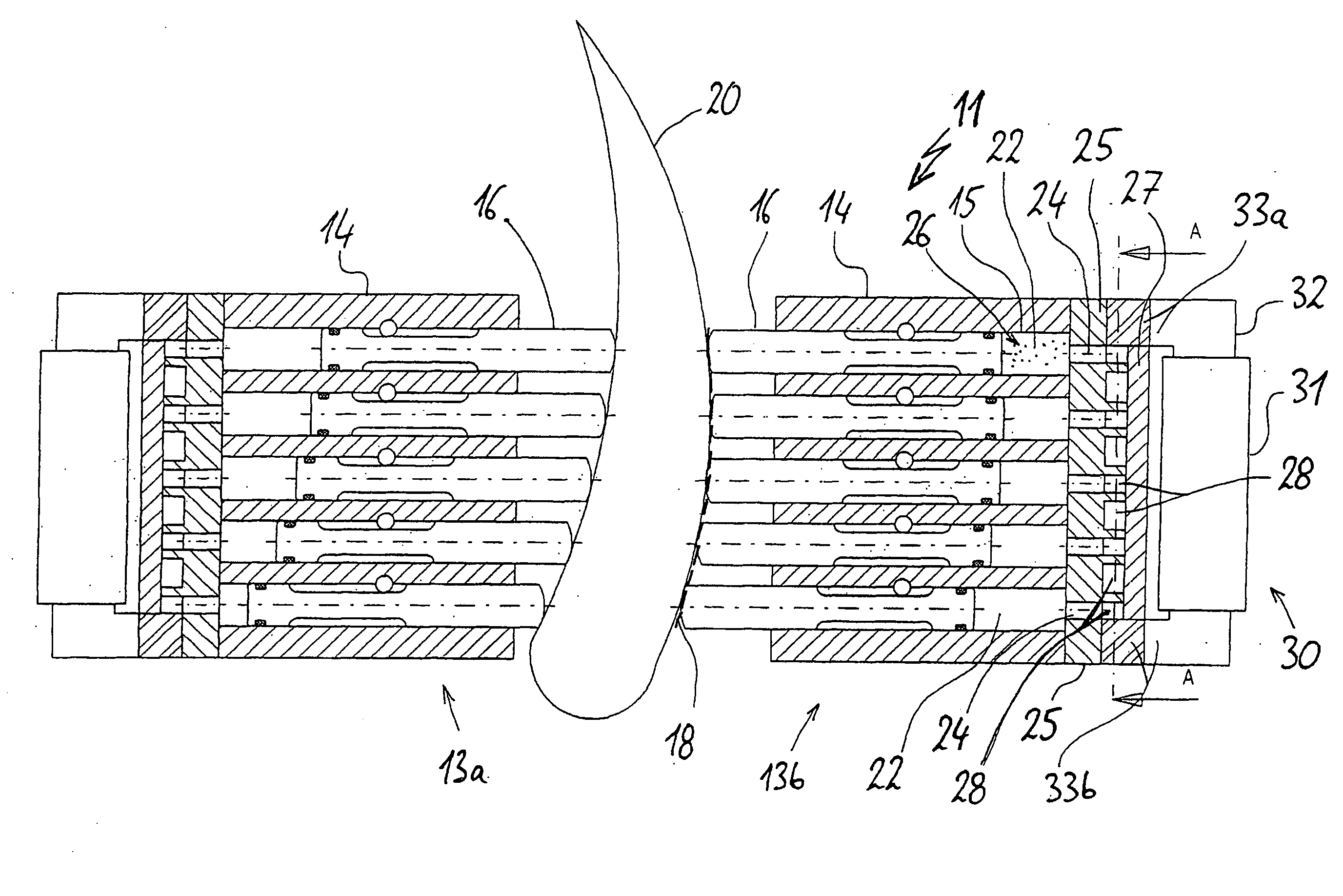
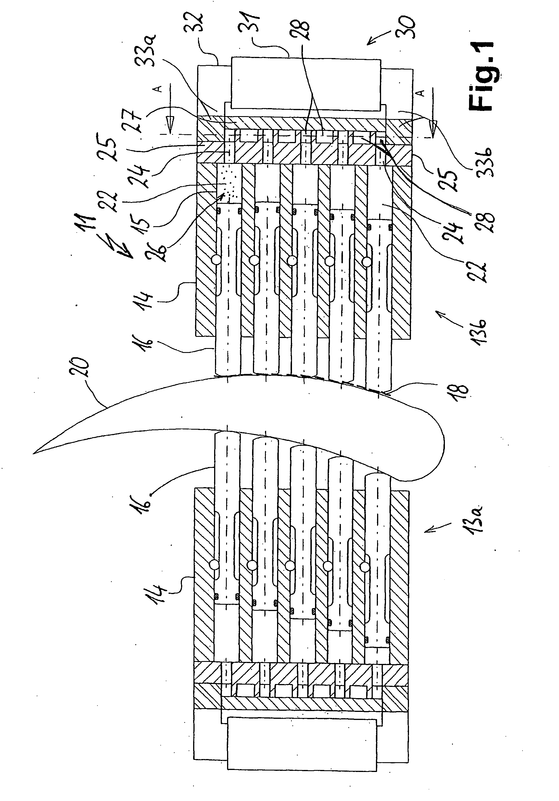
[0028]FIG. 1 shows a clamping device 11 comprising two facing clamping jaws 13a, 13b, which can be moved towards one another. The clamping jaws 13 have linearly displaceable clamping rods 16 guided in rod guides 15. The rods 16 form with their rounded front sides an envelope, which can be looked upon as a clamping side 18 and which is shown in broken line form. In the embodiment shown the rods 16 of both clamping jaws 13a, 13b in each case engage on two sides of a workpiece 20, which has a double curved cross-section. The clamping rods 16 or the clamping sides 18 formed by them engage on the surfaces of workpiece 20 in such a way that by the fixed engagement of each clamping rod it is firmly and immovably clamped thereto.

[0029]At the rear end of clamping rods 16 rod chambers 22 are provided in the rod guides 15 and their size is dependent on the extent to which a rod 16 has been inserted in or extracted from the rod guide 15. By means of channels 24 and depressions in a channel plat...


PUM


Abstract

The invention relates to a clamping device (11) comprising clamping jaws (13) in which a plurality of clamping rods (16) are disposed. The clamping rods (16) are enabled to move by means of an interlinked system of rod chambers (22) and channels (24, 28) in which a magnetorheological fluid (26) is contained. If a magnetic field is applied by means of a magnet (30), the fluid solidifies, the liquid-carrying connection between the rod chambers (22) is interrupted and the rods (16) are fixed in a defined position.

Description

FIELD OF APPLICATION AND PRIOR ART[0001]The invention relates to a clamping jaw according to the preamble of claim 1 and to a clamping device having such a clamping jaw.[0002]It is e.g. known from DE 42 39 180 A1 that for machining purposes sometimes very irregular and in part mechanically sensitive workpieces have to be clamped. This is not possible with a rigidly constructed, solid clamping jaw with an invariable clamping side. For this purpose clamping devices in accordance with DE 42 39 180 A1 have been created having a plurality of elongated clamping rods, which are longitudinally displaceable and which can be applied to a random contour of a workpiece as the clamping side. The clamping rods can be locked in a randomly set position. For this purpose it is inter alia possible to link them with chambers of a hydraulic fluid-filled, communicating system. Through fitted valves it is possible to interrupt the fluid line in the system for each clamping rod and in this way the clampin...

Claims


Application Information

Patent Timeline
Patent Type & Authority Applications(United States)
IPC IPC(8): B25B1/00B25B1/24B25B5/14
CPCB25B5/14B25B1/2421B23Q3/063B23Q3/082B23Q3/1543
Inventor WELLER, HANS-MICHAEL
Owner HAINBUUFU GMBH SHUPANENDE TEHINIKU
Why Eureka
Try Eureka