Piezoelectric vibrating piece and piezoelectric vibrating device

Inactive Publication Date: 2008-07-03
NIHON DEMPA KOGYO CO LTD
View PDF5 Cites 10 Cited by
  • Summary
  • Abstract
  • Description
  • Claims
  • Application Information

AI Technical Summary

Benefits of technology

[0018]According to the above-mentioned format, by using a productive and high quality piezoelectric vibrating piece, a piezoelectric device can be manufactured.
[0019]According to this invention, a piezoelectric vibrating piece and piezoelectric device which has low frequency change to temperature change at a heat treatment can be provi

Problems solved by technology

However, sometimes piezoelectric vibrating devices are not back to a designated primary frequency form a varied frequency.
In such a case, those p

Method used


Image

  • Piezoelectric vibrating piece and piezoelectric vibrating device
  • Piezoelectric vibrating piece and piezoelectric vibrating device
  • Piezoelectric vibrating piece and piezoelectric vibrating device

Examples


Example

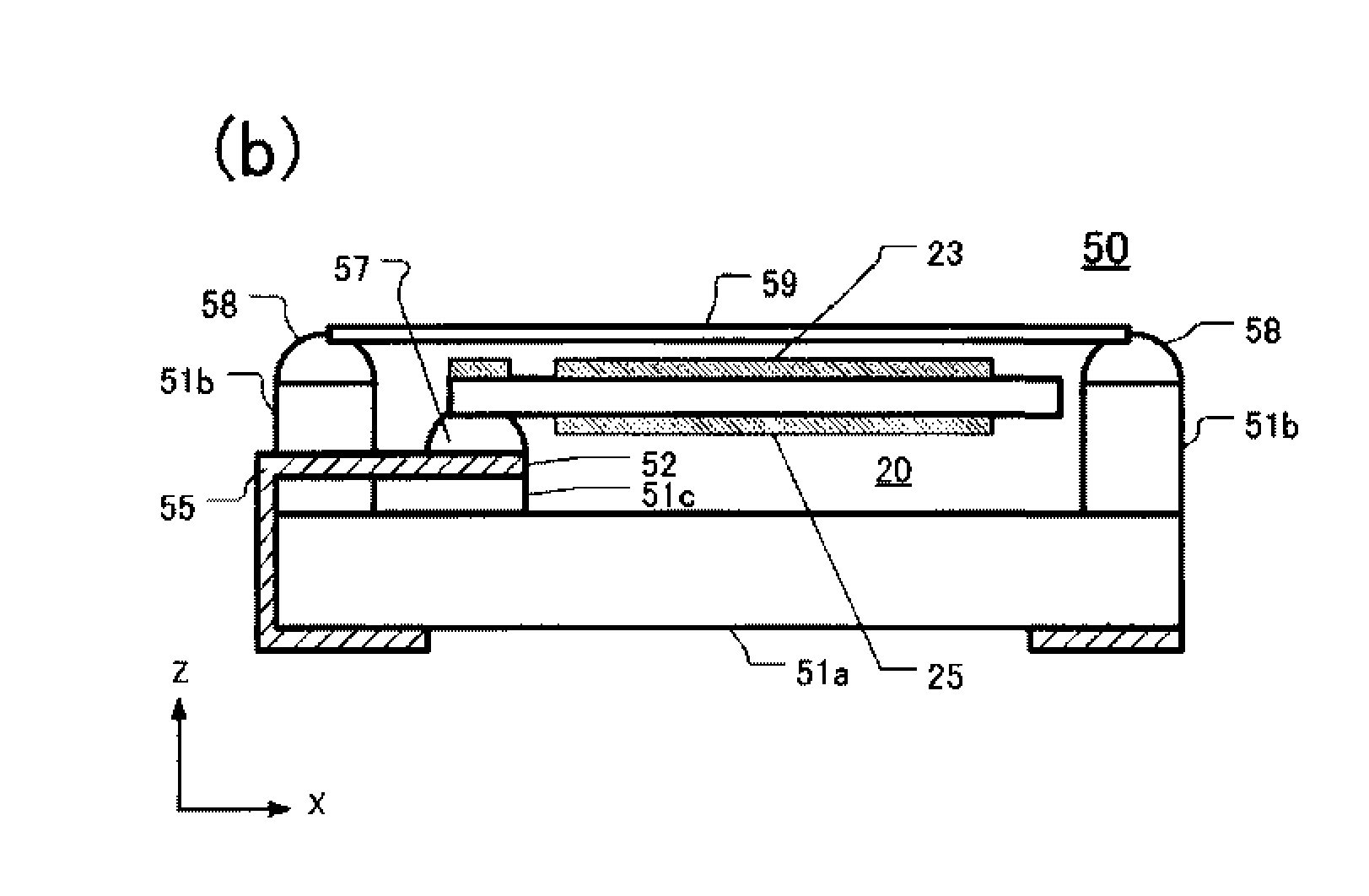
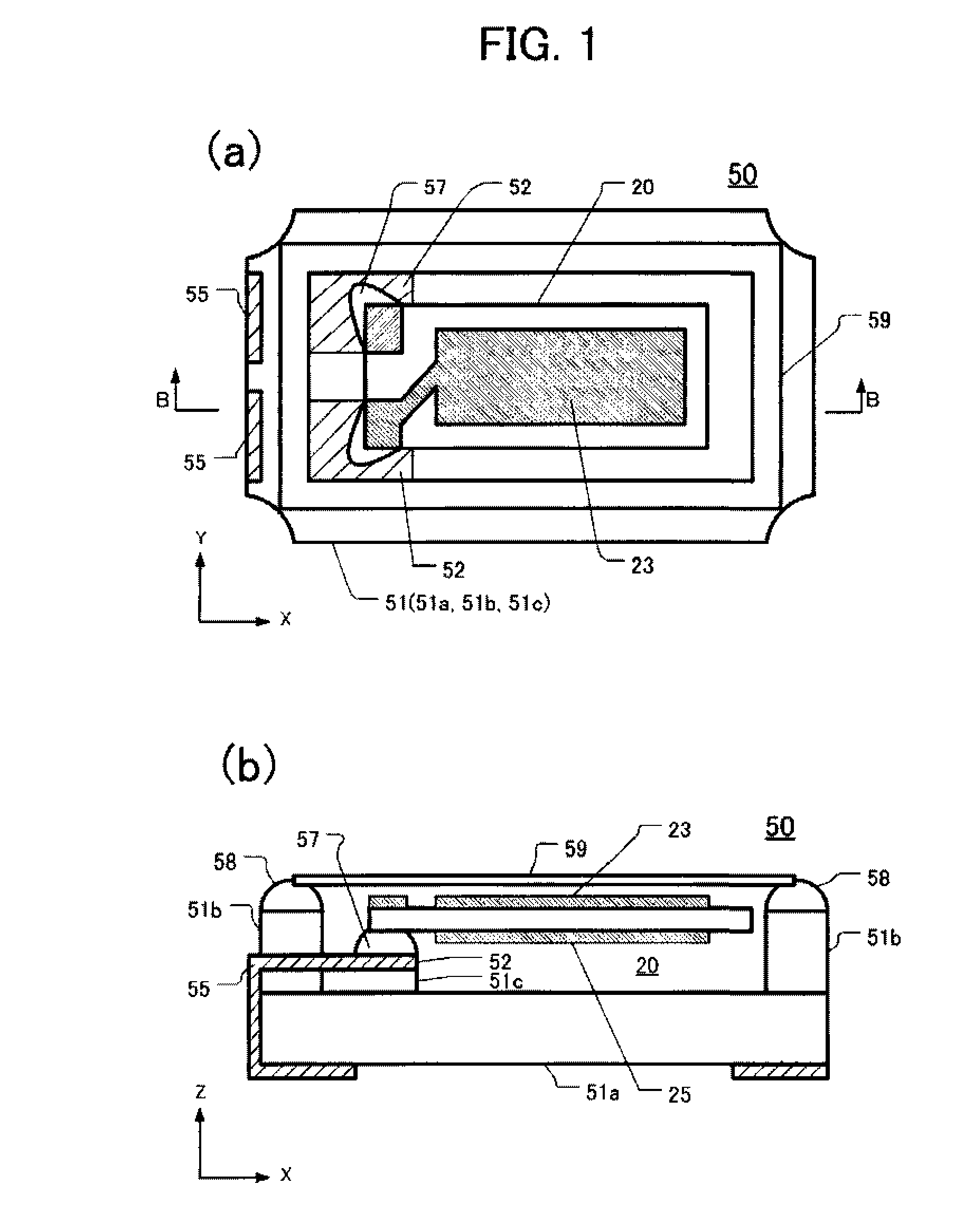
[0026]FIG. 1 shows an embodiment of a piezoelectric vibrating device 50 of this invention. FIG. 1(a) is a top schematic view of the piezoelectric vibrating device 50 and FIG. 1(b) is a cross-sectional view taken form line B-B of FIG. 1(a). In FIG. 1, the piezoelectric vibrating device 50 shows an example of a format of a rectangular shaped piezoelectric vibrating piece 20 and the piezoelectric vibrating device 50 stores the piezoelectric vibrating piece 20 in a package 51. The package 51, for example, as an insulting material, is formed and sintered by laminating several ceramic green sheets comprising a kneaded aluminum oxide.

[0027]In this embodiment, the package 51 comprises a base 51a, a wall 51b and a floor 51c as shown in FIG. 1(b). An internal space of package 51 is formed by covering with the wall 51b, and the piezoelectric vibrating piece 20 is stored in the internal space. Then, the floor 51c is arranged on the base 51a to support the piezoelectric vibrating piece 20 with a...


PUM


Abstract

A piezoelectric vibrating piece having a first and a second surface at an opposing side of the first surface is comprised of an piezoelectric piece having designated coefficient of thermal expansion; a first electrode film having bigger coefficient of thermal expansion than the designated coefficient of thermal expansion and formed on the first surface; and a second electrode film having smaller coefficient of thermal expansion than the designated coefficient of thermal expansion and formed on the second surface.

Description

CROSS-REFERENCE TO RELATED PATENT APPLICATION[0001]This application claims the benefit of Japanese Patent Application No. 2006-354725 filed on Dec. 28, 2006 in the Japan Patent Office, the disclosure of which is incorporated herein in its entirety by reference.FIELD OF THE INVENTION[0002]This application relates generally to the field of piezoelectric devices.BACKGROUND OF THE INVENTION[0003]With the miniaturization of various communication devices or electronic devices, piezoelectric vibrating devices such as crystal oscillators or crystal controlled oscillators need to be downsized. A crystal vibrating piece using piezoelectric vibrating devices is attached to a ceramic package by thermosetting resin. On this occasion, the thermosetting resin is heated up either 150° C. or 250° C. to attach the crystal vibrating piece. Therefore, the crystal vibrating piece is heated up either 150° C. or 250° C. as well. Also, when a packaged piezoelectric vibrating device is mounted to an epoxy l...

Claims


Application Information

Patent Timeline
IPC IPC(8): H01L41/047H01L41/18H01L41/09H01L41/22H01L41/29H01L41/311H03H9/19
CPCH03H9/0547H03H9/132H03H9/1021
Inventor TAKAHASHI, TAKEHIRO
Owner NIHON DEMPA KOGYO CO LTD
Why Eureka
Try Eureka