
Wall element with an antenna device

Active Publication Date: 2008-07-03
AIRBUS OPERATIONS GMBH
View PDF6 Cites 3 Cited by
  • Summary
  • Abstract
  • Description
  • Claims
  • Application Information

AI Technical Summary

Benefits of technology

[0015]Since by the present invention an antenna device is already integrated in the wall element, it is, for example, possible to do without further externally affixed antenna devices, and the number of separate and individually selectable antenna devices may be reduced. In this way both weight and installation space may be saved. Furthermore, by integration of antenna devices in the wall element, electrically conductive materials may be used for the wall element, because by the integrated antenna device it may be possible to emit high-frequency radiation without it being blocked by the conductive materials.
[0036]According to a further exemplary embodiment, the separating material is selected from the group comprising glass fibre materials, Aramide materials, such as Nomex, and honeycomb structure materials. A wall element may thus be provided that features good attenuation characteristics to high-frequency radiation, and good stability while nevertheless being light in weight.

Problems solved by technology

However, it has been shown that data transmission by high-frequency radiation in an aircraft may interfere with the on-board electronics.

Method used


Image

  • Wall element with an antenna device
  • Wall element with an antenna device
  • Wall element with an antenna device

Examples


Embodiment Construction

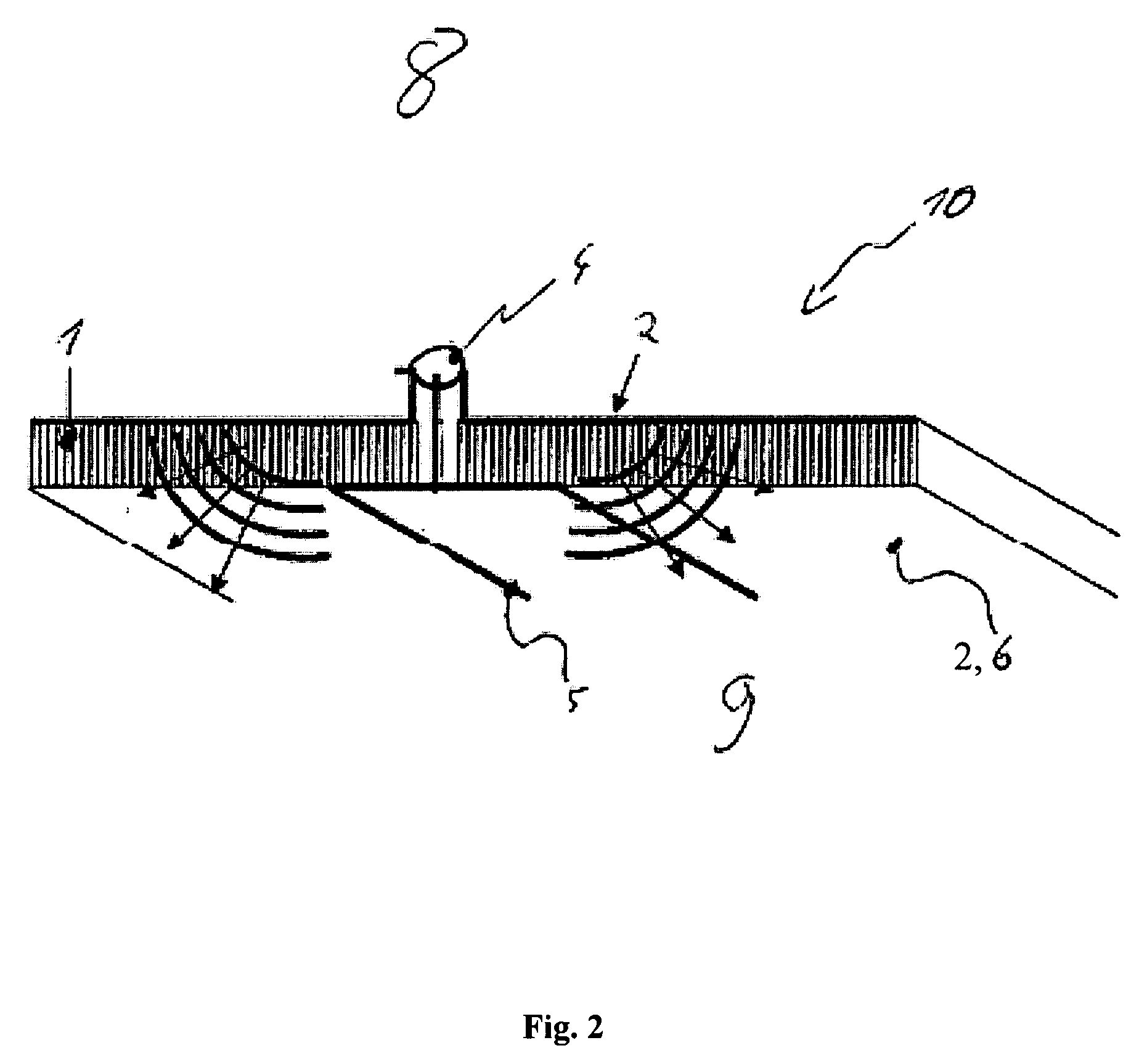
[0043]Identical or similar components in different figures have the same reference characters. The illustrations in the figures are diagrammatic and not to scale.

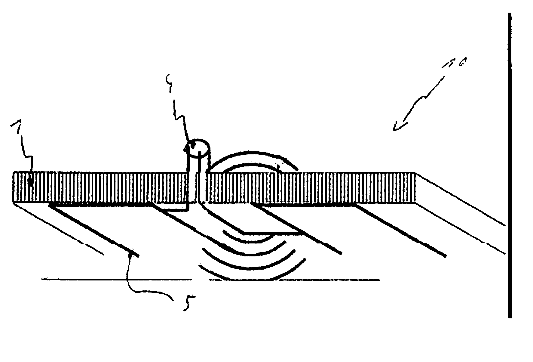
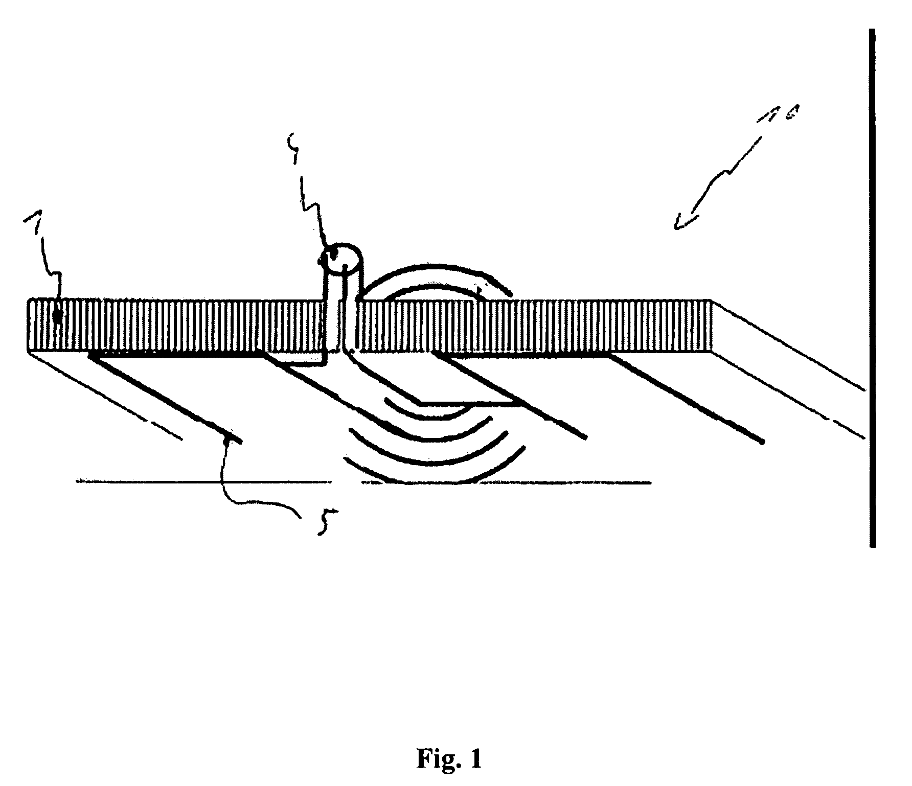
[0044]FIG. 1 shows an exemplary embodiment of the wall element 1 for emitting high-frequency radiation for an aircraft. In this arrangement the wall element 1 comprises an antenna device 5. The antenna device is adapted such that high-frequency radiation may be emitted. The antenna device 5 is integrated in the wall element 1. FIG. 1 shows that the antenna device 5 is integrated in the wall element 1 and that the dimensions of the wall element are not increased or are only slightly increased.

By a high-frequency connection 4 a high-frequency signal may be provided to the antenna device 5. Together it is thus possible to create a passenger module 10 with, for example, a multitude of wall elements. The multitude of wall elements 1 may, for example, be plugged together, and the antenna devices 5 of the wall elements 1 may be in...


PUM


Abstract

A wall element for emitting high-frequency radiation for an aircraft comprises an antenna device. The antenna device is adapted for emitting high frequency radiation. Furthermore, the antenna device is integrated in the wall element.

Description

BRIEF DESCRIPTION OF THE DRAWINGS[0001]This application claims the benefit of the filing date of U.S. Provisional Patent Application No. 60 / 872,215 filed Dec. 1, 2006, the disclosure of which is hereby incorporated herein by reference.BACKGROUND OF THE INVENTION[0002]The present invention relates to a wall element and to a method for emitting high-frequency radiation, to a cabin module for an aircraft, to the use of a wall element in an aircraft, as well as to an aircraft comprising a wall element.[0003]In the modern multimedia world it is necessary, in particular for business travellers, to have access to networking facilities or communication facilities while travelling. There is thus a demand for providing contactability, by radio telephony networks or by internet access, even during air travel.[0004]However, it has been shown that data transmission by high-frequency radiation in an aircraft may interfere with the on-board electronics. In today's commercial aircraft, safety direc...

Claims


Application Information

Patent Timeline
IPC IPC(8): H01Q1/28
CPCH01Q1/28H01Q1/44H01Q17/00H01Q9/27H01Q13/10H01Q1/52
Inventor KEBEL, ROBERTKUERNER, WOLFGANGGYSEMBERG, RUEDY
Owner AIRBUS OPERATIONS GMBH
Learn More