Method and system for signal prediction in predictive coding

a signal prediction and predictive coding technology, applied in the field of data compression methods and systems, can solve the problems of large prediction errors, poor performance, and only work well in conventional methods and systems for predictive coding, and achieve the effects of reducing the amount of data being transmitted, reducing the amount of information being transmitted, and reducing the amount of data being coded

Active Publication Date: 2008-07-03
BEIJING PIANRUOJINGHONG TECH CO LTD
View PDF7 Cites 13 Cited by
  • Summary
  • Abstract
  • Description
  • Claims
  • Application Information

AI Technical Summary

Benefits of technology

[0020]An exemplary embodiment of the present invention provides a video coding method and system that provides a selection between a motion-compensated temporally filtered signal and a motion-compensated prediction signal. In this manner, the present invention reduces the amount of data being transmitted.
[0021]An exemplary embodiment of the present invention provides a video coding method and system that selects between a motion-compensated temporally filtered signal and a motion-compensated prediction signal. In this manner, the present invention reduces the amount of information being transmitted.
[0022]An exemplary embodiment of the present invention provides a video coding method and system that selects between a spatially extrapolated/interpolated signal and a motion-compensated prediction signal. In this manner, the present invention reduces the amount of data being coded.
[0023]An exemplary embodiment of the present invention provides a video coding method and system that selects

Problems solved by technology

The conventional methods and systems for predictive coding only work well when there is strong statistical correlation in the source symbols.
If the correlation is weak, then the prediction will not be able to effectively predict the next source symbol to be encoded and result in large prediction errors and poor performance.
Furthermore, there is usually noise existing in the source and the transmission channel.
The compression itself will also cause quantization noise.
When there is noise in the reference sig

Method used


Image

  • Method and system for signal prediction in predictive coding
  • Method and system for signal prediction in predictive coding
  • Method and system for signal prediction in predictive coding

Examples


Embodiment Construction

[0037]Referring now to the drawings, and more particularly to FIGS. 3-8, there are shown exemplary embodiments of the method and structures of the present invention.

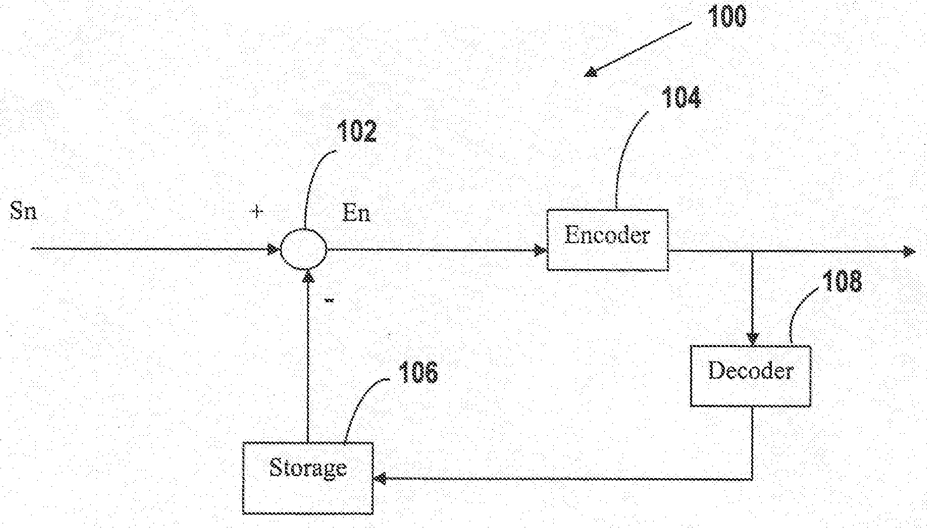
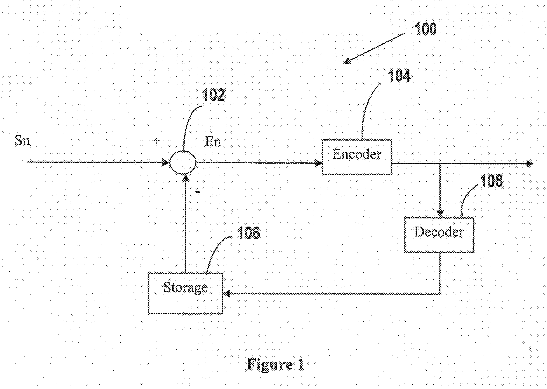
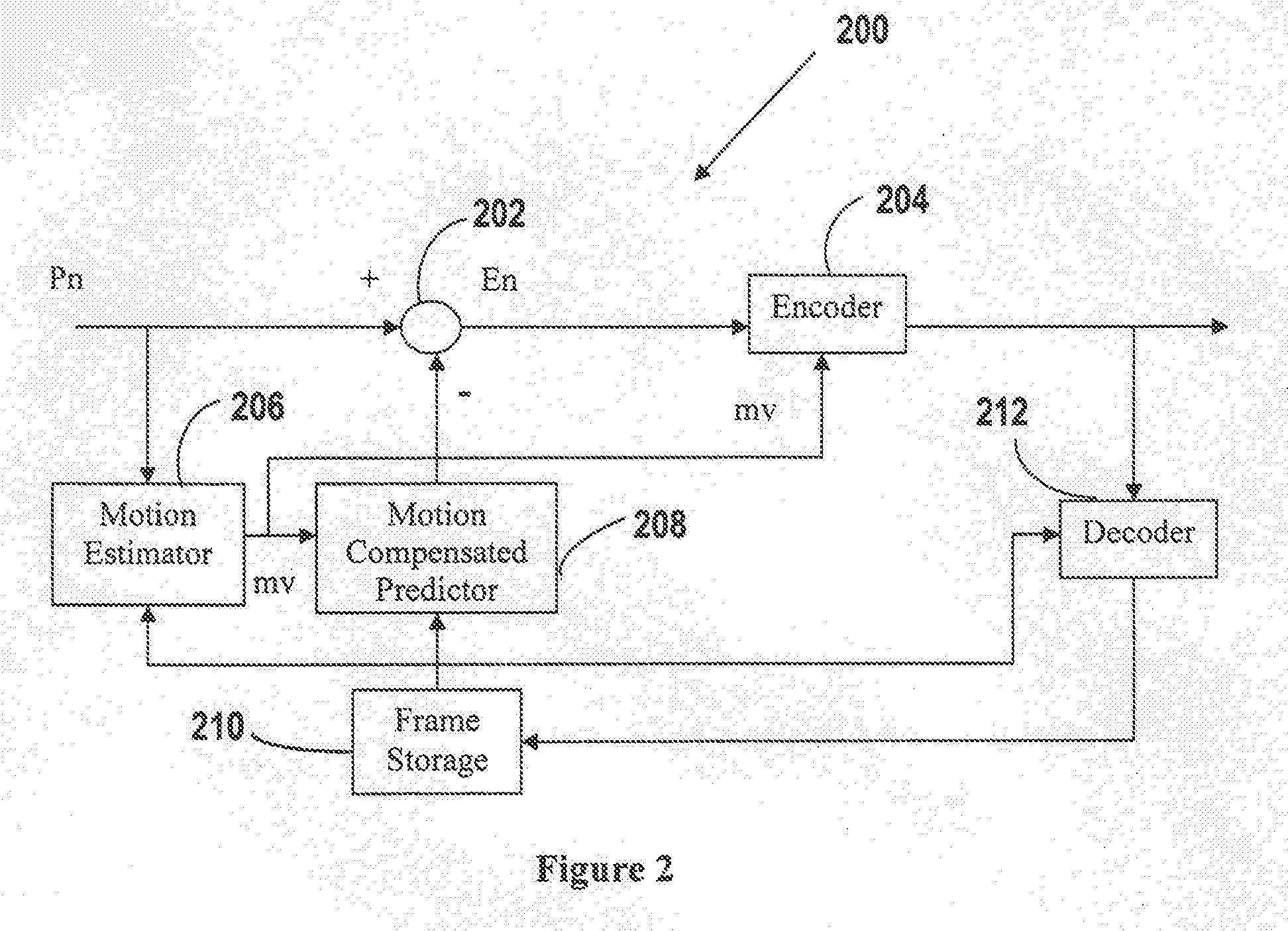
[0038]FIG. 3 illustrates an exemplary system 300 for video coding in accordance with the present invention. The system includes a first comparator 302, a selector 304, an encoder 306, a motion estimator 308, a motion-compensated predictor 310, a second comparator 312, a motion-compensated temporal filter 314, a decoder 316, and a frame storage 318.

[0039]In comparison with the system 200 of FIG. 2, the system 300 of FIG. 3 includes the additional elements of the selector 304, the second comparator 312 and the motion-compensated temporal filter 314. The elements of system 300, which correspond to the elements of system 200, operate in the same manner as described above and a description of their operation is not repeated.

[0040]The motion-compensated temporal filter 314 receives the reference frame data from frame storage 3...


PUM


Abstract

A method (and system) for coding a signal includes comparing a first prediction which is based upon a previously reconstructed signal to an actual signal to determine a first prediction error, comparing a second prediction which is based upon temporal filtering to the actual signal to determine a second prediction error, and selecting one of the first prediction error and the second prediction error.

Description

BACKGROUND OF THE INVENTION[0001]1. Field of the Invention[0002]The present invention relates generally to methods and systems for data compression. More specifically, the present invention describes methods and systems for signal prediction in predictive coding.[0003]2. Description of the Related Art[0004]In predictive coding, instead of coding the source symbol directly, the encoder first generates a predictor of the signal symbol to be coded and computes the prediction error, i.e., the difference between the source symbol and its predictor, then encodes only the prediction error and sends the codeword to the decoder. The decoder decodes the received codeword to obtain the prediction error and performs the same prediction operation at the encoder to generate the same predictor. The decoder then reconstructs the symbol by adding the decoded prediction error to the predictor. To predict the current symbol, the encoder uses the previously decoded symbols to generate a predictor.[0005...

Claims


Application Information

Patent Timeline
IPC IPC(8): H04N7/26
CPCH04N19/105H04N19/176H04N19/147H04N19/172H04N19/567H04N19/117H04N19/19H04N19/82H04N19/523H04N19/61
Inventor LU, LIGANG
Owner BEIJING PIANRUOJINGHONG TECH CO LTD
Why Eureka
Try Eureka