Image processing device and image processing method

a technology of image processing and image, applied in the field of image processing device and image processing method, can solve the problems of requiring a wide output dynamic range, unable to output an image with such a wide dynamic range to an output device having a narrow dynamic range without processing an image, and it is difficult to accurately separate an illumination component and a reflectance component in an image. , to achieve the effect of high luminance region, low luminance region, and high contrast imag

Active Publication Date: 2008-07-03
KONICA MINOLTA INC
View PDF4 Cites 32 Cited by
  • Summary
  • Abstract
  • Description
  • Claims
  • Application Information

AI Technical Summary

Benefits of technology

[0015]An image processing device and an image processing method according to an aspect of the invention generate multiple images having different edge preservation performances based on an original image, and synthesize the multiple images based on edge information. In the synthesis, the generated images are synthesized in such a manner that an image of an edge portion in the generated image having a low edge preservation performance is replaced by the generated image having a high edge preservation performance. The inventive image processing device and image processing method are advantageous in properly preserving the edge portion while suppressing occurrence of a halo effect or the like in the edge portion.

Problems solved by technology

The linear-logarithmic sensor has another drawback that an extremely wide output dynamic range is required if the logarithmic characteristic is converted into the linear characteristic.
As a result, it is impossible to output an image with such a wide dynamic range to an output device having a narrow dynamic range without processing an image.
It is technically difficult to accurately separate an illumination component and a reflectance component in an image.
As a result, the reflectance component in the extracted illumination component may also be compressed in compressing the illumination component, which may lower the contrast in the entire image.
This may cause an edge defect such as a pseudo edge in the linear object or the rod object.

Method used


Image

  • Image processing device and image processing method
  • Image processing device and image processing method
  • Image processing device and image processing method

Examples


first embodiment

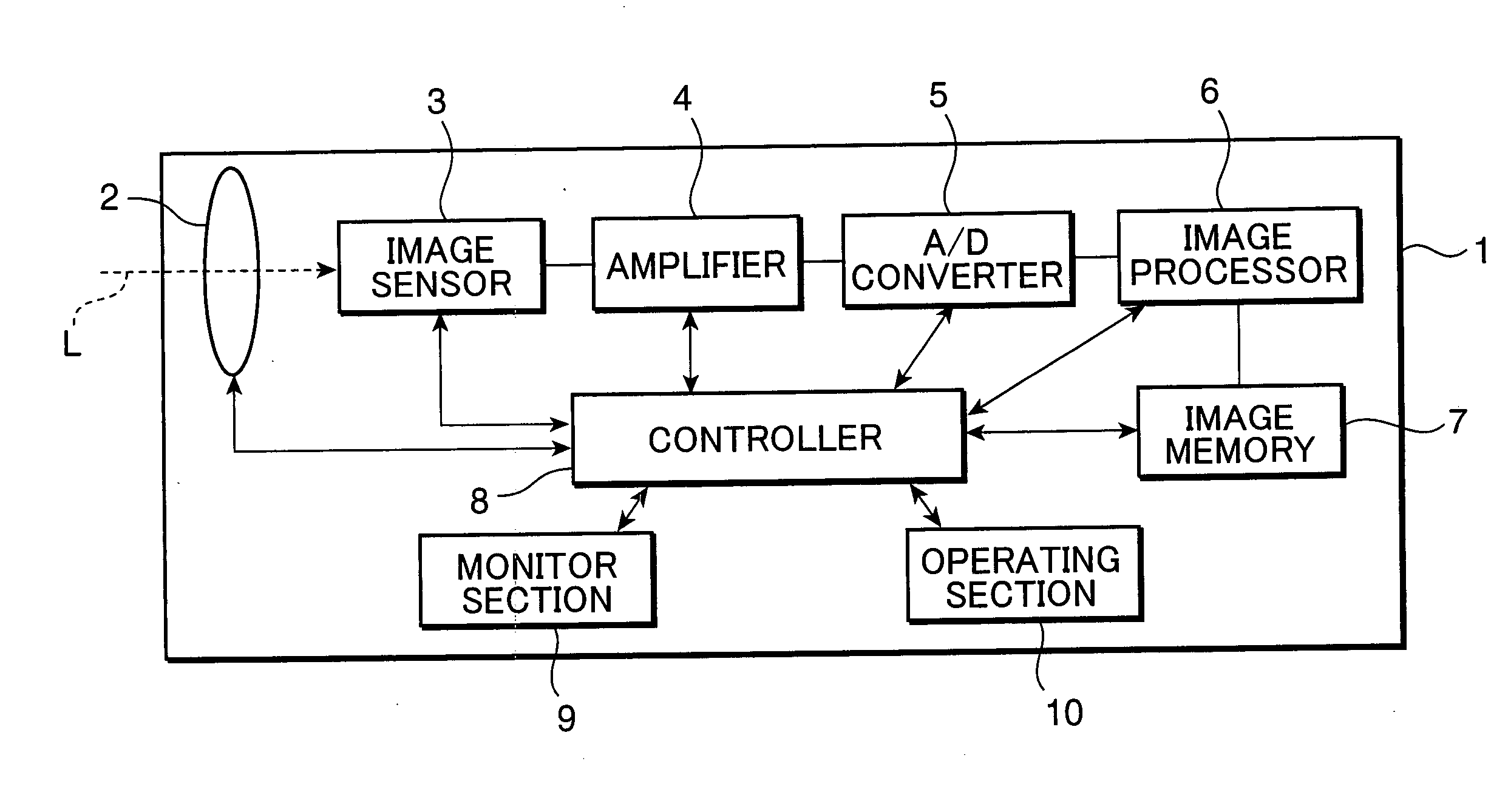
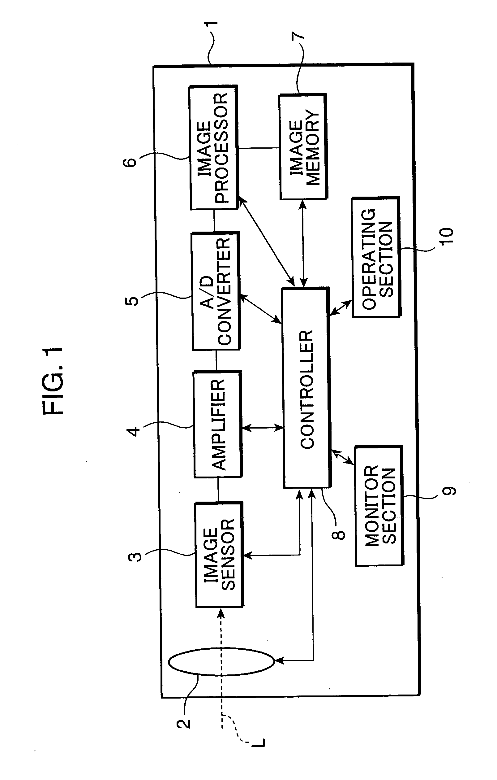
[0030]FIG. 1 is a block diagram showing elements primarily relating to an imaging processing of a digital camera, as an example of an image sensing apparatus to which an image processing device in accordance with a first embodiment of the invention is applied. Referring to FIG. 1, a digital camera 1 includes a lens section 2, an image sensor 3, an amplifier 4, an analog-to-digital (A / D) converter 5, an image processor 6, an image memory 7, a controller 8, a monitor section 9, and an operating section 10.

[0031]The lens section 2 functions as a lens aperture for allowing light from a subject i.e. an optical image to pass. The lens section 2 constitutes an optical lens system for guiding the subject light toward the image sensor 3 disposed in the camera body. The lens section 2 has a diaphragm (not shown) and a shutter (not shown) for regulating the amount of light transmitted through the lens aperture. The controller 8 controls driving of the diaphragm or the shutter.

[0032]The image s...

second embodiment

[0058]FIG. 8 is a block diagram showing a configuration of a high contrast processor 60a in a second embodiment of the invention. The high contrast processor 60a is primarily different from the high contrast processor 60 shown in FIG. 3 in that a first edge preserver 61c and a second edge preserver 61d are provided in place of the first edge preserver 61a and the second edge preserver 61b. The first edge preserver 61a and the second edge preserver 61b are operative to obtain an illumination component whose edge component is preserved by using an edge preserving filter such as an epsilon filter or a bilateral filter. The first edge preserver 61c and the second edge preserver 61d are operative to obtain an illumination component whose edge component is preserved by performing hierarchical low-pass filter processing. In the following, an arrangement of the first edge preserver 61c and the second edge preserver 61d, and the hierarchical low-pass filter processing are described.

[0059]FIG...

third embodiment

[0071]FIG. 11 is a block diagram showing a configuration of a high contrast processor 60b in a third embodiment of the invention. Referring to FIG. 11, the high contrast processor 60b is primarily different from the high contrast processor 60 or 60a in that a first dynamic range compressor 61e and a second dynamic range compressor 61f are provided in place of the first edge preserver 61a and the second edge preserver 61b, or the first edge preserver 61c and the second edge preserver 61d. The first edge preserver 61a and the second edge preserver 61b (see FIG. 3), and the first edge preserver 61c and the second edge preserver 61d (see FIG. 8) process an image before dynamic range compression. In other words, in the first and the second embodiments, the illumination component L to be outputted from the adder 64 undergoes dynamic range compression by a dynamic range compressor provided after the high contrast processor 60 or 60a. In the third embodiment, an image which has undergone a ...


PUM


Abstract

An image processing device and an image processing method of the invention generate multiple images having different edge preservation performances based on an original image, and synthesize the multiple images based on edge information. In the synthesis, the generated images are synthesized in such a manner that an image of an edge portion in the generated image having a low edge preservation performance is replaced by the generated image having a high edge preservation performance.

Description

[0001]This application is based on Japanese Patent Application No. 2006-351339 filed on Dec. 27, 2006, the contents of which are hereby incorporated by reference.BACKGROUND OF THE INVENTION[0002]1. Field of the Invention[0003]The present invention relates to an image processing device and an image processing method that enable to preserve an edge in a high-quality image.[0004]2. Description of the Background Art[0005]In recent years, in an image sensing apparatus such as a digital camera, as a high-quality image is demanded, a technology of expanding a luminance range i.e. a dynamic range of a subject image to be captured by an image sensor is required. In expanding the dynamic range, there is known an image sensor (hereinafter, called as “linear-logarithmic sensor”) having a photoelectric conversion characteristic (hereinafter, also called as “linear / logarithmic characteristic”) comprised of a linear characteristic and a logarithmic characteristic. An image which is captured by the...

Claims


Application Information

Patent Timeline
Patent Type & Authority Applications(United States)
IPC IPC(8): G06K9/40H04N5/235
CPCH04N5/208H04N5/20
Inventor KATAGIRI, TETSUYASATO, KAZUCHIKA
Owner KONICA MINOLTA INC
Why Eureka
Try Eureka