
Bearing Bush and Compound Movement Using the Same

a technology of bearing bush and compound movement, which is applied in the direction of bearing unit rigid support, sliding contact bearing, mechanical apparatus, etc., can solve the problems of increasing device size and cost, housing inclination with respect to the spline shaft, and unstable contact between the bearing bush and the spline shaft, so as to reduce the contact area, reduce the contact force, and minimize the effect of sliding resistan

Inactive Publication Date: 2008-07-03
THK CO LTD
View PDF2 Cites 14 Cited by
  • Summary
  • Abstract
  • Description
  • Claims
  • Application Information

AI Technical Summary

Benefits of technology

[0012]The present invention has been made in view of the above-mentioned problems. Therefore, it is an object of the present invention to provide a bearing bush in which the clearance between the bearing bush and the shaft member is eliminated to thereby eliminate backlash therebetween, enabling the shaft member to perform advancing / retreating movements in a satisfactory manner, and in which the burden of dimension control for both the bearing bush and the shaft member is lessened, thus achieving a reduction in production cost.Means for Solving the Problems
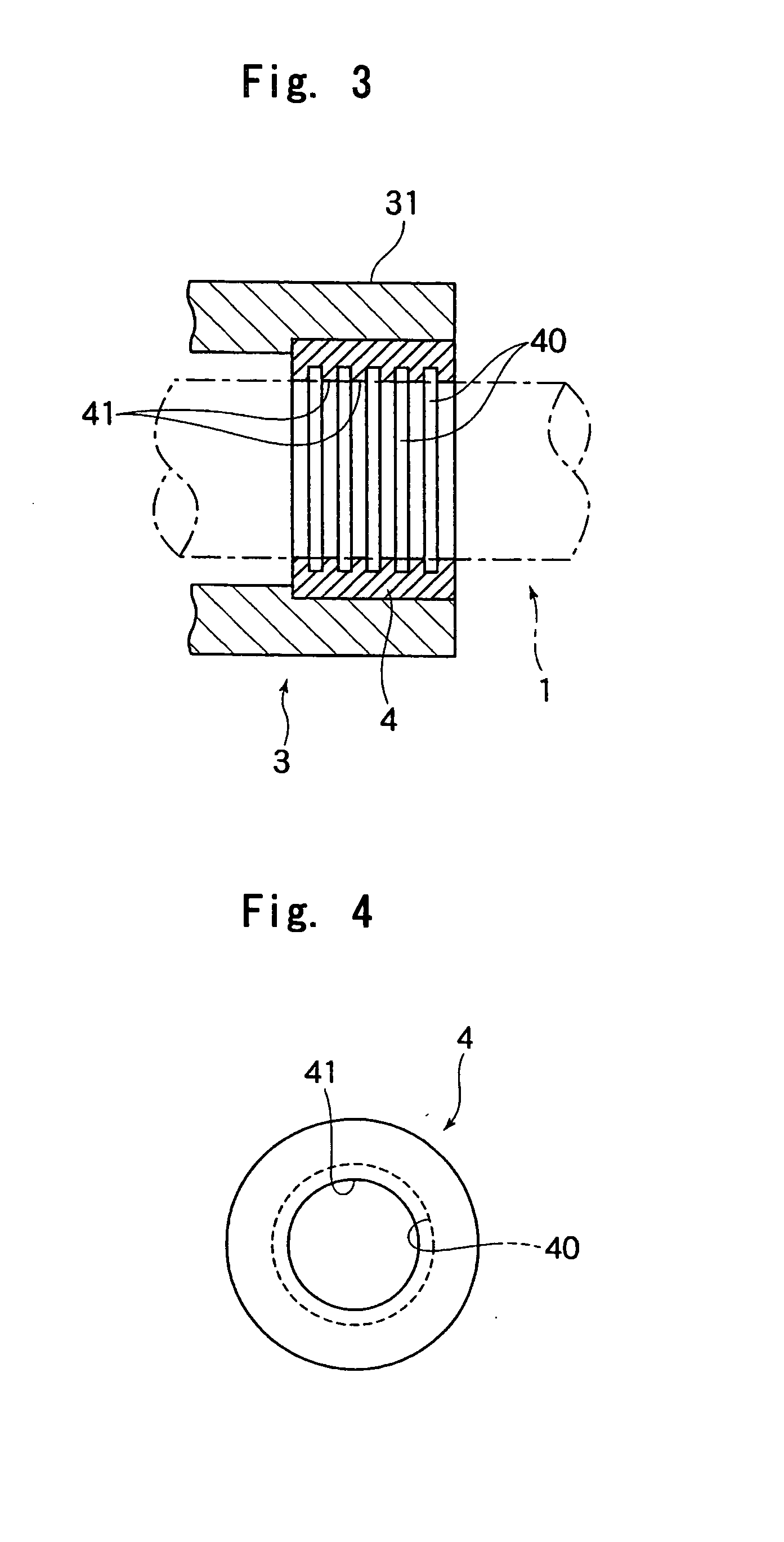
[0014]According to the present invention, grooves are formed sequentially at predetermined intervals in the inner peripheral surface of the bearing bush, so even if the bearing bush is fit-engaged with the shaft member by interference fit, the sliding contact surface of the bearing bush in press contact with the shaft member is crushed relatively easily, making it possible to reduce the press contact force with respect to the shaft member. Further, it is also possible to reduce the contact area between the bearing bush and the shaft member.
[0015]Thus, it is possible to minimize the sliding resistance between the bearing bush and the shaft member while eliminating the clearance therebetween, making it possible to achieve enhancement in the accuracy of the advancing / retreating movements of the shaft member with respect to the bearing bush. Further, due to the formation of a plurality of grooves in the inner peripheral surface of the bearing bush, the sliding contact surface of the bearing bush in press contact with the shaft member is crushed and deformed relatively easily, so it is possible to minimize the sliding resistance of the bearing bush with respect to the shaft member without having to perform strict control on the inner diameter dimension of the bearing bush, also making it possible to produce the bearing bush at so much the lower cost.
[0016]The bearing bush used in the present invention may be formed of metal or synthetic resin. However, from the viewpoint of reducing the press contact force generated when fit-engaging the bearing bush and the spline shaft with each other in a state of an interference fit, synthetic resin is more preferable.
[0017]The bearing bush of the present invention can be used in the above-described compound movement device. In the compound movement device, the advancement / retreating of the spline shaft is supported by the large number of balls with which the spline nut is provided. When the spline shaft advances or retreats at high acceleration or deceleration, the vibration due to the rolling of the balls acts on the spline shaft. However, in the present invention, when the advancing / retreating movements of the spline shaft are supported by using the bearing bush, the bearing bush is in press contact with the spline shaft, so the attenuation effect with respect to the vibration of the spline shaft is improved. Thus, even when the spline shaft advances or retreats at high acceleration or deceleration, the requisite positioning time for the spline shaft tends to be shorter. As a result, it is possible to shorten the tact time of an operation using this compound movement device, thus making it possible to produce machines and apparatuses with satisfactory productivity.
[0018]Further, the bearing bush of the present invention can be used for supporting the advancing / retreating movements of an output rod of a linear motor actuator. A known example of a linear motor actuator is composed of a magnet rod on which a large number of magnetic poles are arranged and a coil member loosely fitted around the magnet rod and adapted to drive the magnet rod in the axial direction. When this magnet rod is used as the output rod, it is necessary to support the advancing and retreating movements of the magnet rod by a bearing member. When the bearing bush of the present invention is used as the bearing member, it is possible to eliminate the clearance between the bearing bush and the magnet rod and to minimize the sliding resistance between the two members, making it possible to enhance the accuracy of the advancing and retreating movements of the magnet rod with respect to the bearing bush.

Problems solved by technology

In providing the rotation transmitting member on the housing, if the rotation transmitting member is superimposed on the spline nut, the outer diameter of the rotation transmitting member becomes rather large, resulting in an increase in the device size and an increase in cost.
On the other hand, when such the stepped cylindrical member is used as the housing and the spline nut and the rotation transmitting member are deviated from each other in the axial direction of the housing, a radial load applied to the housing from the rotation transmitting member (i.e., load perpendicular to the axial direction of the spline shaft) is allowed to act on the spline nut as a moment load, and if there is no support at all for the forward end of the small diameter portion of the housing with respect to the spline shaft, there is a disadvantage in that the housing will incline with respect to the spline shaft.
However, when the resin bearing bush fixed to the small diameter portion of the housing is thus fitted onto the spline shaft in a state of a clearance fit, due to the presence of a clearance, although extremely small, between the spline shaft and the bearing bush, the contact between the bearing bush and the spline shaft becomes rather unstable and the sliding resistance of the housing with respect to the spline shaft undergoes fluctuation or the like, so there arises a problem in that the precision in the axial advancing / retreating movement of the housing is likely to be impaired.
Further, strict control of the inner diameter dimension of the bearing bush and the outer diameter dimension of the spline shaft is required, which leads to an increase in production cost.

Method used


Image

  • Bearing Bush and Compound Movement Using the Same
  • Bearing Bush and Compound Movement Using the Same
  • Bearing Bush and Compound Movement Using the Same

Examples


Embodiment Construction

[0029]In the following, a bearing bush according to the present invention will be described in detail with reference to the accompanying drawings.

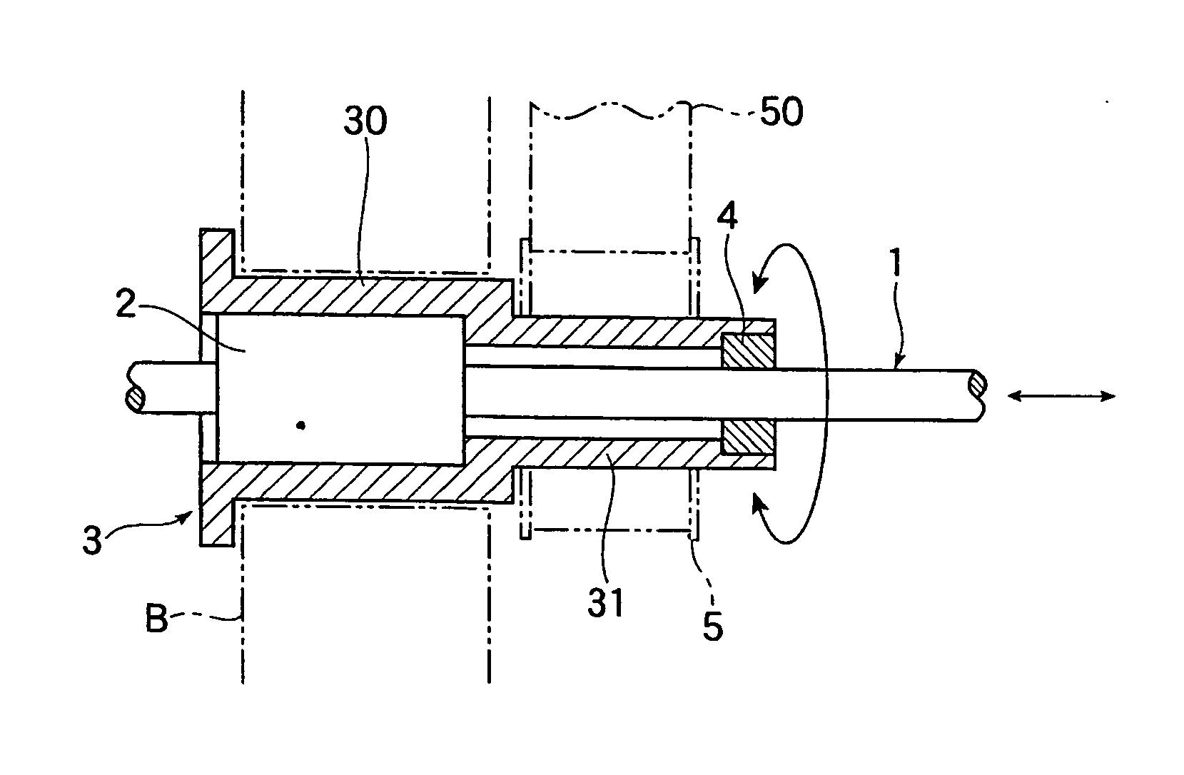
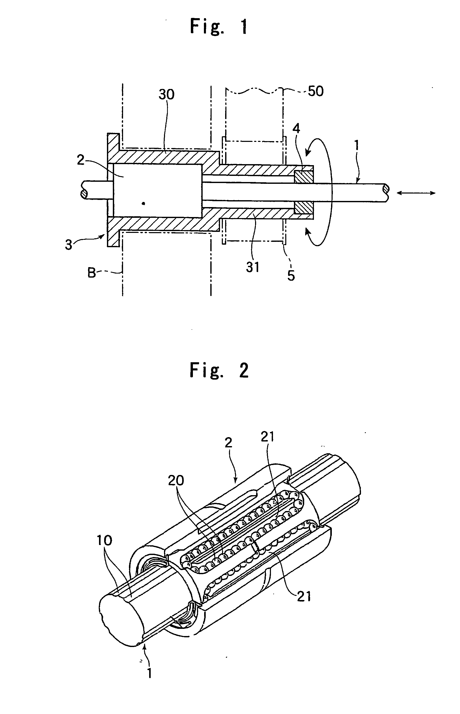
[0030]FIG. 1 shows an example of a compound movement device supporting advancing and retreating movements of a spline shaft by using a bearing bush according to the present invention. This device is used as the main shaft of a tool replacement device or the like, and is composed of a spline shaft 1 used as the main shaft, a spline nut 2 capable of reciprocating in the axial direction of the spline shaft 1, a housing 3 for retaining the spline nut 2 and supported so as to be rotatable with respect to a stationary portion B, and a bearing bush 4 provided at one end of the housing 3, for guiding the advancing and retreating of the spline shaft 1 with respect to the housing 3.

[0031]The spline shaft 1 is caused to make axial advancing and retreating movements by a ball screw device, a hydraulic cylinder, a pneumatic cylinder, or the like (all o...


PUM


Abstract

Provided is a bearing bush enabling excellent advancing and retreating movements of a shaft member by eliminating a clearance between the bearing bush and the shaft member to eliminate a backlash therebetween, capable of reducing a load of dimension control on both the bearing bush and the shaft member, and capable of being manufactured at a low cost. The bearing bush (4) for supporting the reciprocating movement of the shaft member (1) in an axial direction has a receiving hole through which the shaft member (1) is passed. Grooves (40) are sequentially formed at predetermined intervals in an inner peripheral surface of the bearing bush (4) facing the receiving hole. An inner diameter of the receiving hole is formed to be equal to or smaller than an outer diameter of the shaft member (1), and the bearing bush is press-fitted to an outer peripheral surface of the shaft member (1) in a state of a so-called interference fit.

Description

TECHNICAL FIELD[0001]The present invention relates to a bearing bush for supporting axial advancing and retreating movements of a shaft member, such as a spline shaft. For example, the present invention relates to a bearing bush used to support advancing and retreating movements of a spline shaft of a compound movement device having the spline shaft as the main shaft and capable of imparting a rotating motion to the spline shaft while causing the spline shaft to advance and retreat.BACKGROUND ART[0002]A main shaft of an automatic work supply device or of an automatic tool replacing device in an NC machine tool is required to be capable of making a rotational movement with high accuracy while freely advancing or retreating in the axial direction. In this connection, a combination of a spline shaft and a spline nut is used as means for supporting an axial movement of the main shaft and transmitting rotational torque to the main shaft.[0003]In particular, in a ball spline, in which a s...

Claims


Application Information

Patent Timeline
IPC IPC(8): F16C31/02F16C33/10H02K41/02F16C23/04F16C29/02F16C29/06F16C31/06F16C33/20F16C35/02H02K41/03
CPCF16C31/02F16C33/20F16C33/10F16C29/02
Inventor MICHIOKA, HIDEKAZUIIDA, KATSUYAMATSUMOTO, TAKASHIISHIZAKA, MASAYUKI
Owner THK CO LTD
Learn More