[0013]It is an object of the present invention to provide a dental
implant of the aforementioned kind, which may be easily inserted by a dentist and avoids the drawbacks of the state of the art while having a simple structure and a simple and cost-effective producibility.
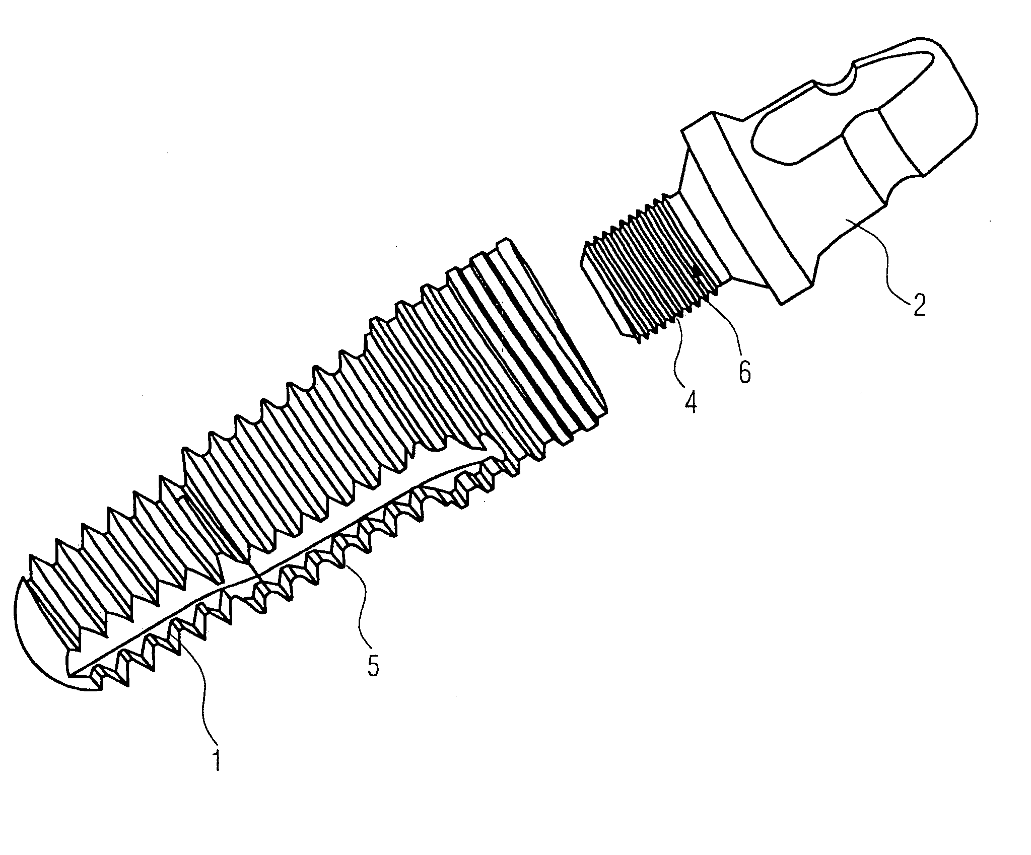
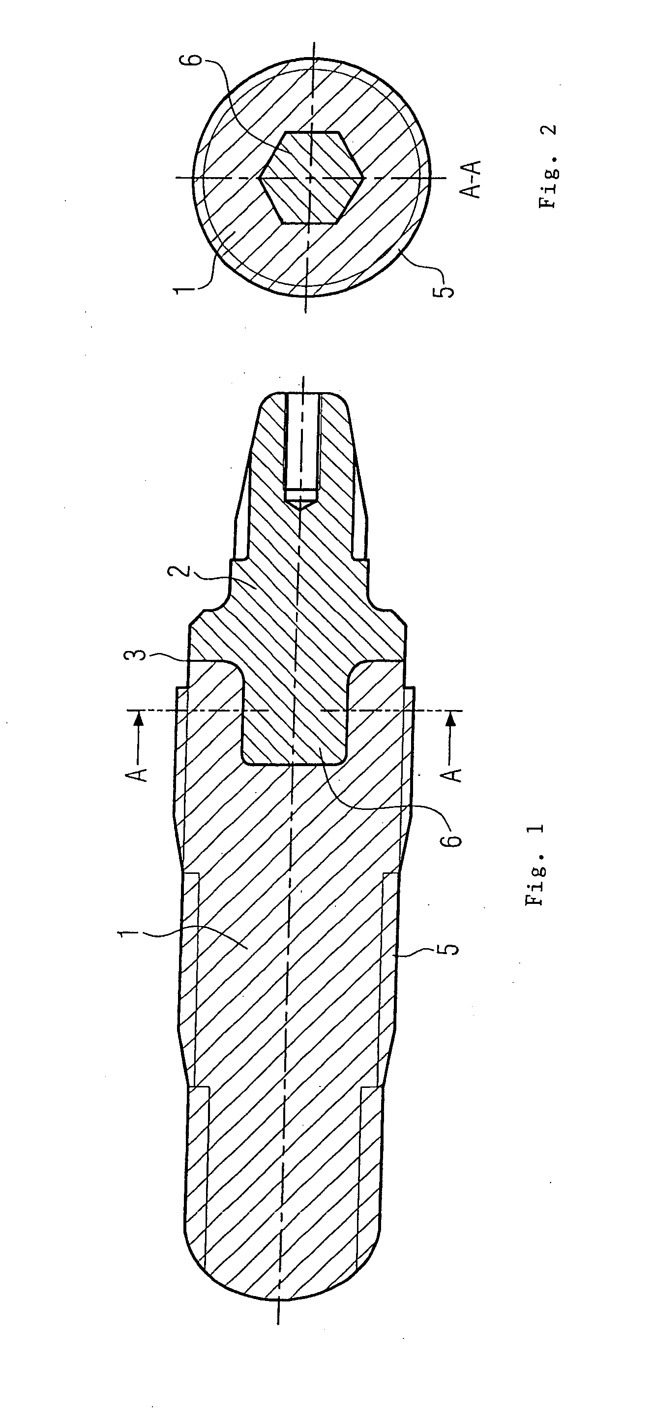
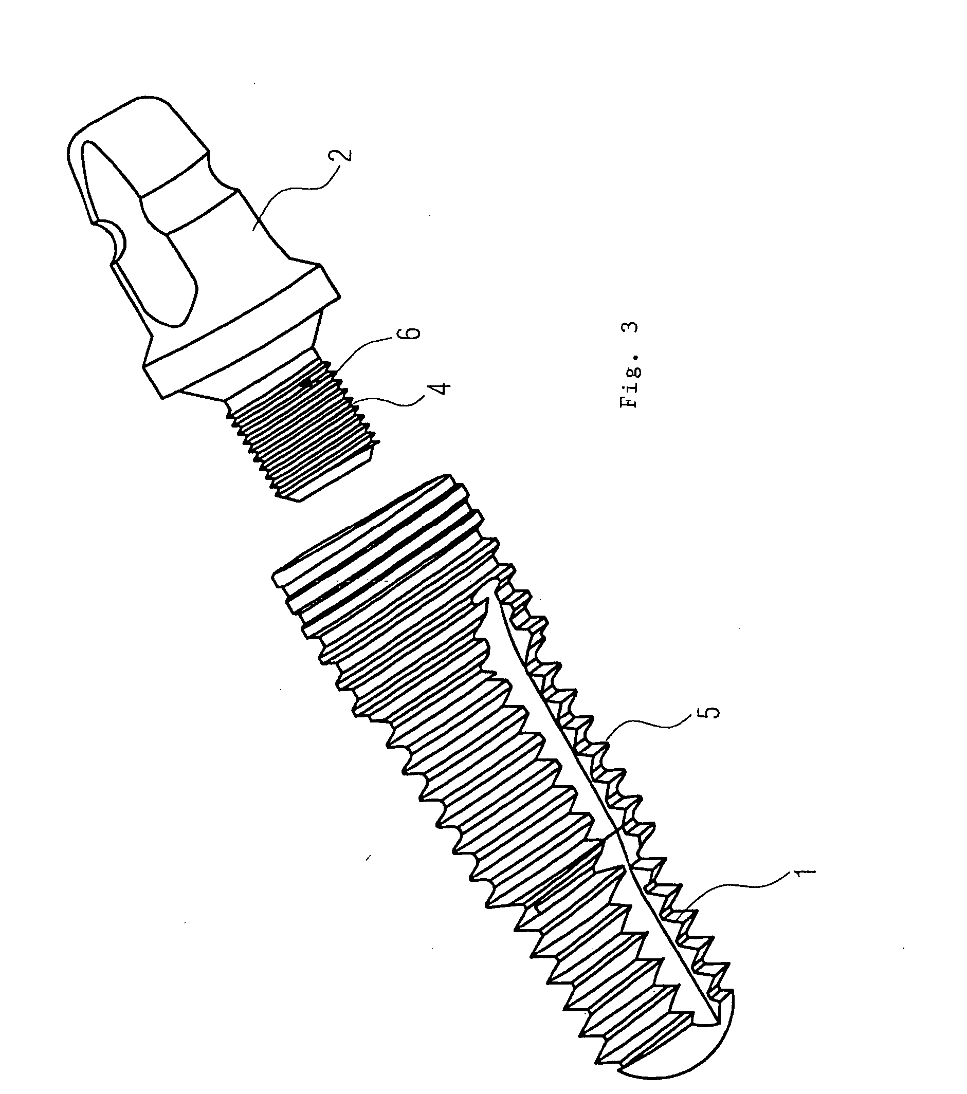
[0015]According to the present invention, a dental
implant is formed integrally or in one part, wherein the enossal portion is made of a metallic material and is connected integrally with the coronal portion which is made of a
ceramic material. The inventive dental implant is thus finished in the factory and may be inserted directly by the dentist. It is not required to assemble parts during the operation. Therewith, it is also prevented that the
assembly of the coronal portion onto the enossal portion is not performed correctly. In particular, the formation of a gap between the enossal portion and the coronal portion is excluded, since this may be reliably monitored during the factory-made production. In addition, it is prevented that an
adhesive or any other bonding material, which is inevitably present in the transitional area of a two-part dental implant being assembled by a dentist, escapes and may in particular enter into the bone, where it may cause strong reactions and problems for the patient.
[0016]The inventive dental implant is thus pre-produced in the factory and may be formed such that a setup or a crown may be mounted directly onto the coronal portion or that the coronal portion must be processed only slightly. In both cases, the working time of the dentist is shortened, such that the inventive dental implant may be inserted economically. In addition, mistakes during the
assembly of the dental implant and its
insertion are excluded. Consequently, as a whole, a high degree of comfort and security is achieved.
[0018]Within the scope of the present invention, there result different embodiments for the connecting portion. The same is produced as a force-fit joining connection, for example by
welding,
soldering, or bonding. It is further provided to form the connecting portion in a form-fit manner, in addition to a
welding, bonding, or
soldering process. The form-fit
coupling results in an increased
mechanical strength. It is also possible to couple the coronal portion and the enossal portion by a thread or a bayonet joint and to subsequently bond, weld, or solder the parts, if required. Also, an increased
mechanical strength is achieved, in particular in a coronal portion made of a
ceramic material.
[0019]Furthermore, it is provided within the scope of the present invention that the coronal portion and the enossal portion engage in a form-fit manner, for example by concave or convex partial portion. Therewith, also the joining surface is enlarged, such that the
mechanical load capacity may be increased.
[0020]It is particularly preferable if the inventive dental implant is dimensioned such that the connecting portion between the coronal portion and the enossal portion, when the dental implant is inserted, lies within the gingival area of the patient. Preferably, the toothridge abuts substantially against the ceramic material of the coronal portion. This serves, on the one hand, to enhance the optical appearance and, on the other hand, to enhance the physical and medical acceptance by the patient.

