Method for manufacturing field emission cathode

Active Publication Date: 2008-07-03
TSINGHUA UNIV +1
View PDF9 Cites 17 Cited by
  • Summary
  • Abstract
  • Description
  • Claims
  • Application Information

AI Technical Summary

Problems solved by technology

However, the typical method for manufacturing the insulative layer is relatively complex and, thus, is not fit for mass production.
Furthermore, the toughness and pliability of the field emission cathode is relatively poor and is generally not fit for flexible display devices.

Method used


Image

  • Method for manufacturing field emission cathode
  • Method for manufacturing field emission cathode
  • Method for manufacturing field emission cathode

Examples


Embodiment Construction

[0025]Reference will now be made to the drawings to describe embodiments of the present method for manufacturing a field emission cathode, in detail.

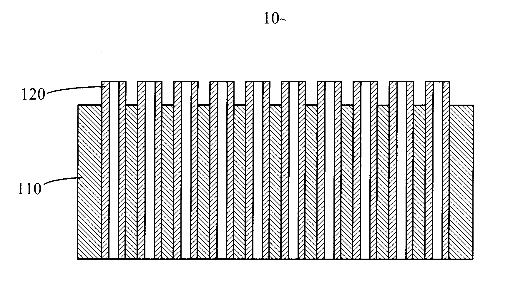
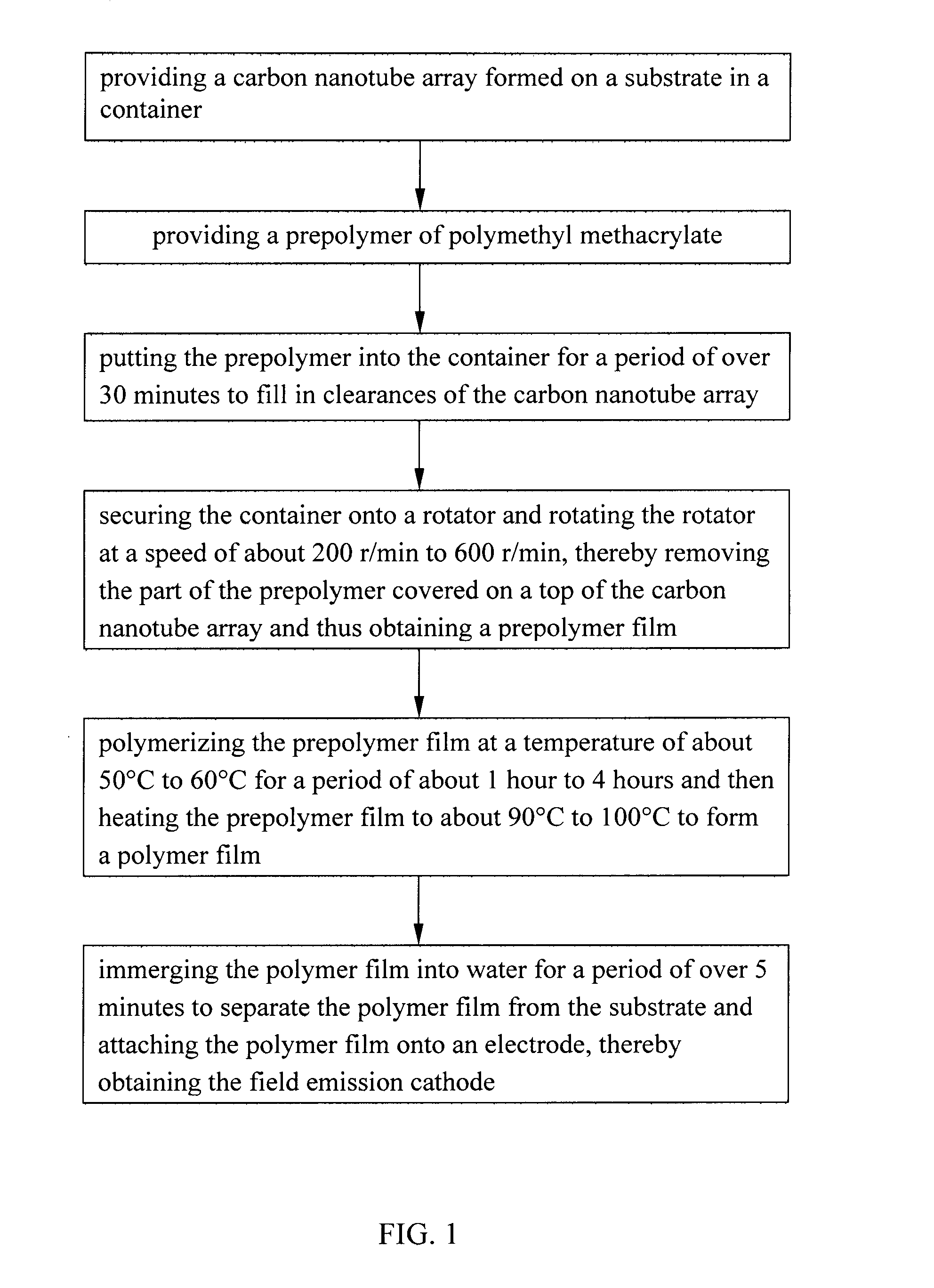
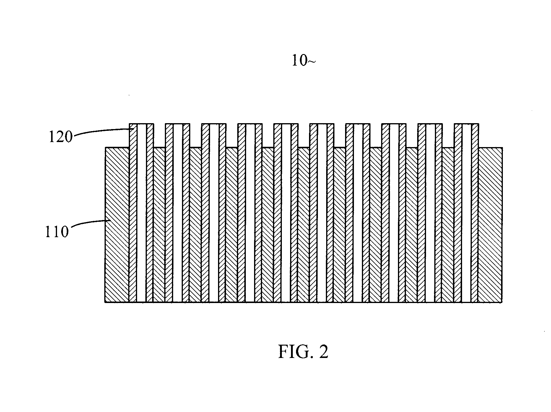
[0026]Referring to FIG. 1, a method for manufacturing a field emission cathode includes the following steps: (a) providing a carbon nanotube array formed on a substrate in a container; (b) providing a prepolymer of polymethyl methacrylate (PMMA); (c) putting the prepolymer into the container and permitting the prepolymer to settle for a period of over 30 minutes to fill in clearances of the carbon nanotube array; (d) securing the container onto a rotator and rotating the rotator at a speed of about 200 r / min to 600 r / min, thereby removing the part of the prepolymer covered on a top end of the carbon nanotube array and, thus, obtaining a prepolymer film; (e) polymerizing by first holding the prepolymer film at a temperature of about 50° C. to 60° C. for a period of about 1 hour to 4 hours and then heating the prepolymer film to about 90°...


PUM


Abstract

A method for manufacturing a carbon nanotube / polymer composite includes the steps of: (a) providing a carbon nanotube array formed on a substrate in a container; (b) providing a prepolymer of polymethyl methacrylate (PMMA); (c) putting the prepolymer into the container for a period of over 30 minutes to fill in clearances of the carbon nanotube array; and (d) polymerizing the prepolymer film at a temperature of about 50° C. to 60° C. for a period of about 1 hour to 4 hours and then heating the prepolymer film to about 90° C. to 100° C. to form a polymer film, the carbon nanotube array thereby being embedded within the polymer film.

Description

BACKGROUND OF THE INVENTION[0001]1. Field of the Invention[0002]The invention relates to methods for manufacturing field emission cathodes and, particularly, to a method for manufacturing a field emission cathode including a carbon nanotube array.[0003]2. Discussion of Related Art[0004]Carbon nanotubes (CNTs) produced by means of arc discharge between graphite rods were first discovered and reported in an article by Sumio Iijima, entitled “Helical Microtubules of Graphitic Carbon” (Nature, Vol. 354, Nov. 7, 1991, pp. 56-58). Carbon nanotubes are electrically conductive along their length, are chemically stable, and can have, individually, very small diameters (much less than 100 nanometers) and large aspect ratios (length / diameter). Due to these and other properties, it has been suggested that carbon nanotubes can play an important role in fields such as microscopic electronics, field emission devices, thermal interface materials, etc.[0005]Generally, a CNT field emission device inc...

Claims


Application Information

Patent Timeline
IPC IPC(8): H01J9/02
CPCH01J9/025
Inventor ZHANG, QIU-CENSONG, PENG-CHENGLIU, CHANG-HONGFAN, SHOU-SHAN
Owner TSINGHUA UNIV
Why Eureka
Try Eureka