Chain transmission device

a transmission device and chain technology, applied in the direction of gearing, gearing elements, hoisting equipment, etc., can solve the problems of increasing the engagement sound, reducing the engagement sound, and reducing the kinetic energy of the engagement of the roller or bushing with the sprocket, so as to reduce the engagement sound and reduce the kinetic energy. the effect of the engagement sound and the reduction of the engagement sound

Inactive Publication Date: 2008-07-03
TSUBAKIMOTO CHAIN CO
View PDF6 Cites 11 Cited by
  • Summary
  • Abstract
  • Description
  • Claims
  • Application Information

AI Technical Summary

Benefits of technology

[0035]First, the kinetic energy at the engagement of the roller or bushing with the sprocket is reduced, and the engagement sound is reduced as a result.
[0036]Second, since the timing of the impact of the rollers or bushings with the sprocket is irregular, noises having an order determined by the number of sprocket teeth are reduced. Furthermore, since the difference between the overall sounds and each rotational order sound, i.e. each periodic sound, is large, the rotational order sounds become less noticeable.
[0037]A preceding roller or bushing of the standard chain first abuts a tooth surface of a sprocket on the back side thereof with reference to the direction of rotation. At the start of engagement of the following roller or bushing with the sprocket, the following roller or bushing abuts the back side of a next tooth substantially in the direction of a tangent line. Shock due to relative movement of the preceding roller or bushing is therefore small. Furthermore, since the shock at abutment is small at the start of engagement, the noise due to shock is reduced.
[0038]At disengagement of the roller or bushing from the sprocket, a preceding roller or bushing pivotably moves relative to the following roller or bushing about the center of the following roller or bushing in an arcuate path having a radius equal to the chain pitch of the standard chain. Thus, the path of the following roller is arcuate when the sprocket is the reference. Since the preceding roller or bushing initially abuts the front surface of a tooth in the direction of its rotation, the roller or bushing can easily move from its abutment position. Therefore, the preceding roller or bushing can smoothly disengage from the sprocket without being wedged between opposed tooth surfaces.

Problems solved by technology

For example, in a high power engine operating at a high rotational speed, the load on the timing transmission and its contribution to the overall noise produced by the engine become significant.
The principal source of timing transmission noise is the engagement sound generated as the chain engages the sprockets.
However, as the load on the transmission increases, the tension in the chain also increases, resulting in greater levels of engagement sounds.
Vibration proofing materials have not proven capable of suppressing these noises adequately.
The collision results in vibration and noise at the beginning of engagement.
Moreover, vibration and noise increase as the number of sprocket teeth is increased.

Method used


Image

  • Chain transmission device
  • Chain transmission device
  • Chain transmission device

Examples


Embodiment Construction

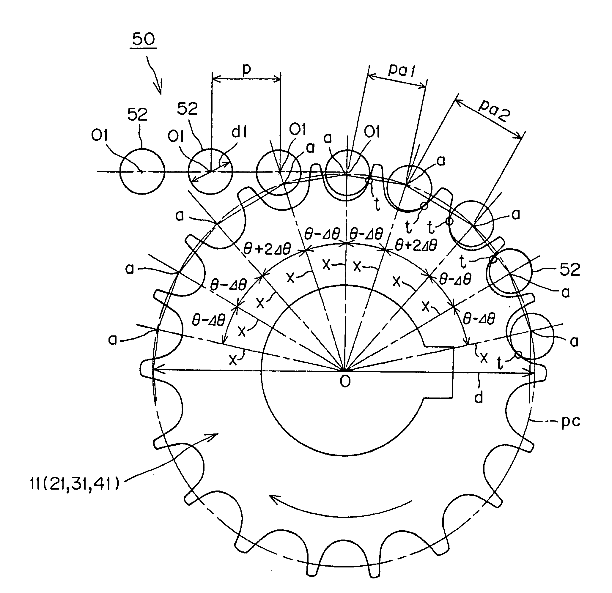
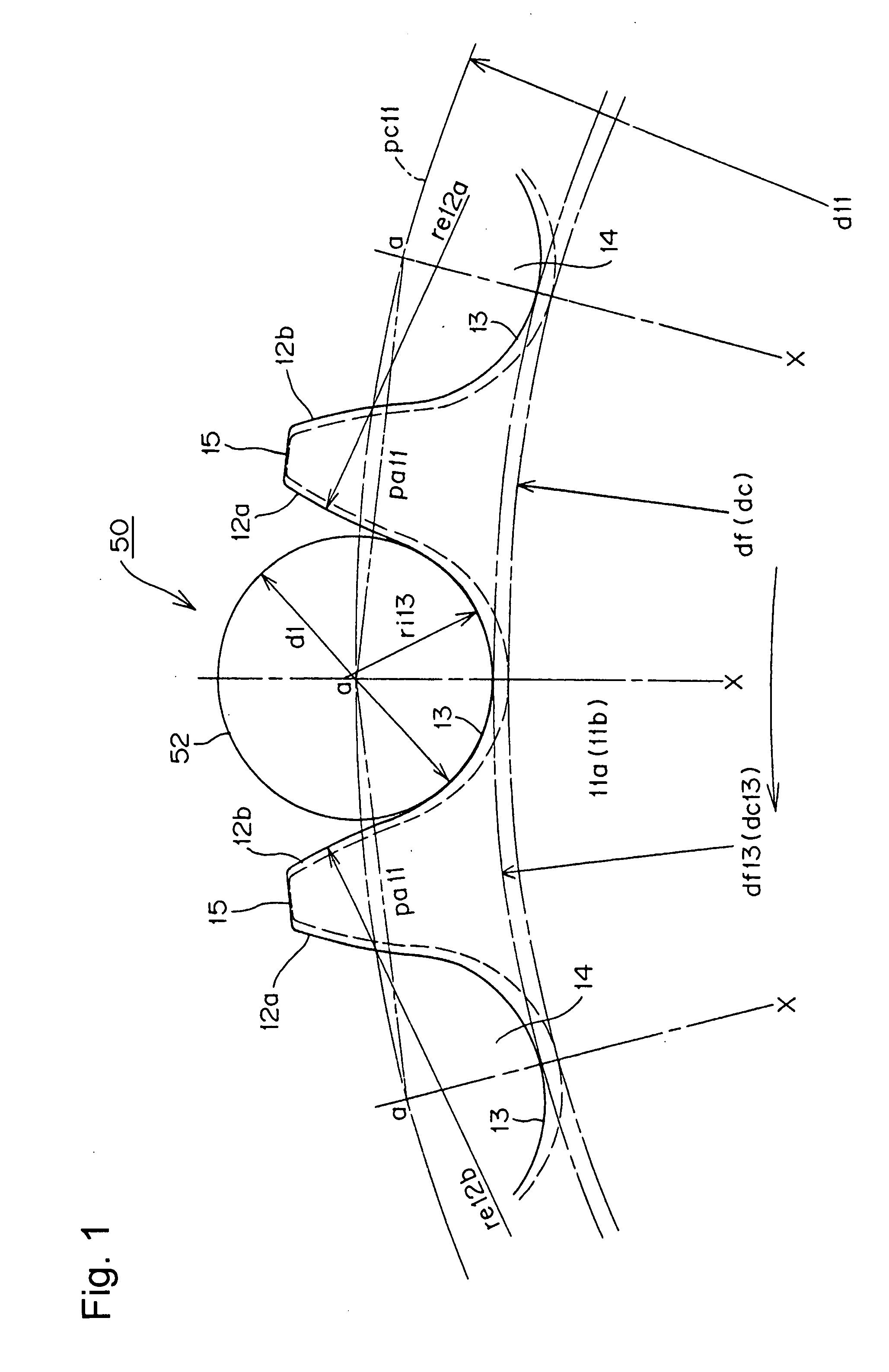
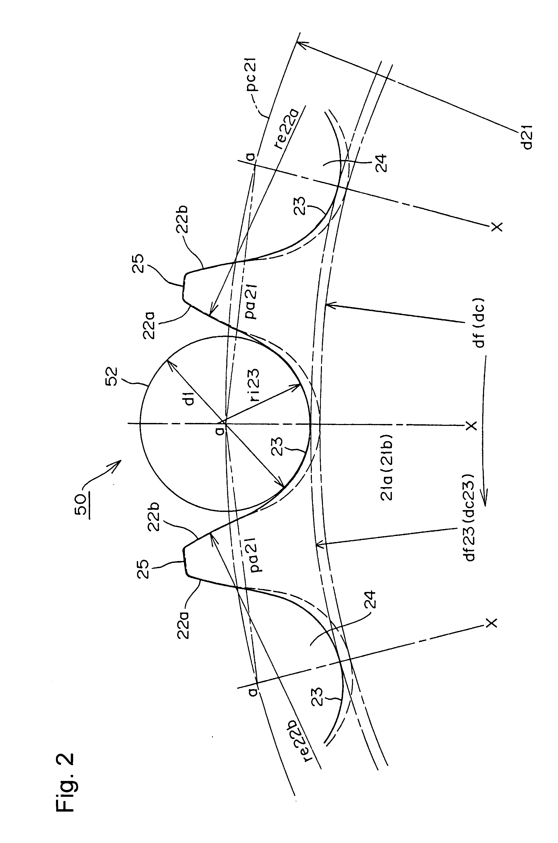
[0049]In a chain transmission incorporating a standard roller chain or a standard rollerless bushing chain, if a sprocket of the transmission has at least two different tooth form pitch angles, arranged irregularly around the pitch circle, and the root diameter of the sprocket is larger than the root diameter of a standard sprocket, vibration and noise generated when the standard chain engages the sprocket are reduced, and the standard chain disengages from the sprocket smoothly.

[0050]In the sprocket of a preferred chain transmission according to the invention, a plurality of sprocket teeth are separated from one another by tooth gaps. Facing surfaces of adjacent teeth are continuous with a tooth gap bottom. In the tooth form of the sprocket, the root diameter of the tooth gap bottom circle is larger than the root diameter of a standard sprocket, that is, a sprocket in which the teeth conform to the ISO tooth form. The teeth of the sprocket have at least two different tooth form pit...


PUM


Abstract

In a chain transmission a standard ISO roller chain meshes with a modified sprocket having a root diameter larger than the root diameter of a standard sprocket designed for use with the standard chain. The angular tooth pitches can be either of two kinds. In a first version, the sprocket has two irregularly distributed tooth pitches, θ−Δθ and θ+2Δθ, there being two tooth pitches θ−Δθ for each tooth pitch θ+2Δθ. In a second version, the sprocket has three angular tooth pitches, θ−Δθ, θ, and θ+Δθ, in equal numbers, also distributed irregularly.

Description

CROSS-REFERENCE TO RELATED APPLICATION[0001]This application claims priority from Japanese patent application 2006-353489, filed Dec. 27, 2006. The disclosure of Japanese patent application 2006-353489 is incorporated by reference.FIELD OF THE INVENTION[0002]The invention relates to a chain transmission in which noises, generated when a roller of a standard roller chain or a bushing of a standard rollerless bushing chain engages with a sprocket tooth, are reduced, and in which the roller or bushing smoothly disengages the sprocket.BACKGROUND OF THE INVENTION[0003]A chain transmission in which a chain is engaged with a driving sprocket and one or more driven sprockets has been widely used as a timing transmission in automobile engines for driving the valve-operating cam or cams from the engine crankshaft.[0004]Recent demand for higher power automobile engines, coupled with public consciousness of environmental problems, has led to the development of engines that produce high levels o...

Claims


Application Information

Patent Timeline
Patent Type & Authority Applications(United States)
IPC IPC(8): F16H55/30F16H7/06
CPCF16H55/08F16H2055/306F16H55/30F16G13/02F16H7/06
Inventor HIRAI, AKIRASAKURA, SHUNJISUGASAWA, SHIGENOBUKUROHATA, JUNYAOGAWA, TAKESHI
Owner TSUBAKIMOTO CHAIN CO
Why Eureka
Try Eureka