Starter

a technology of starting device and engine, which is applied in the direction of electric generator control, electric control, instruments, etc., can solve the problems of long longer time to restart the engine, and vehicle cannot move quickly, so as to improve the mountability

Active Publication Date: 2008-07-03
HITACHI ASTEMO LTD
View PDF25 Cites 87 Cited by
  • Summary
  • Abstract
  • Description
  • Claims
  • Application Information

AI Technical Summary

Benefits of technology

[0011]According to the present invention, the state where the pinion and the ring gear remain meshing with each other in the engine stop mode can continue without a magnetic switch employing a new solenoid. Thus, mountability can be improved.

Problems solved by technology

Consequently, the automatic engine stop and start system has a problem that it takes long time to restart the engine and the vehicle cannot move promptly.
Particularly, when the pinion and the ring gear collide with each other before meshing, it takes longer time to restart the engine.
However, in the technique, since the plunger stopper uses a solenoid only for holding the plunger of the magnetic switch, the technique has a problem of low mountability.

Method used


Image

  • Starter
  • Starter
  • Starter

Examples


first embodiment

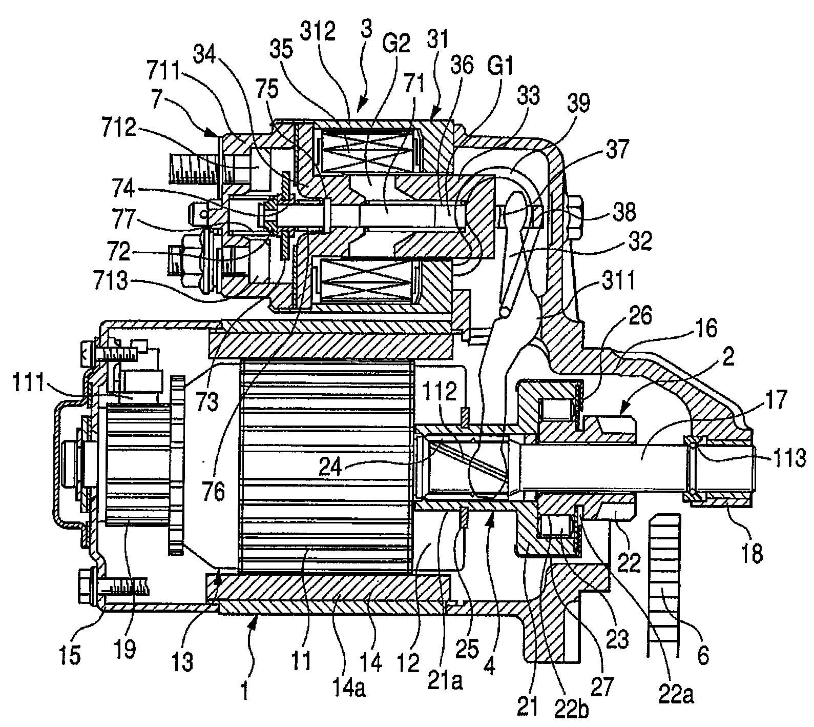
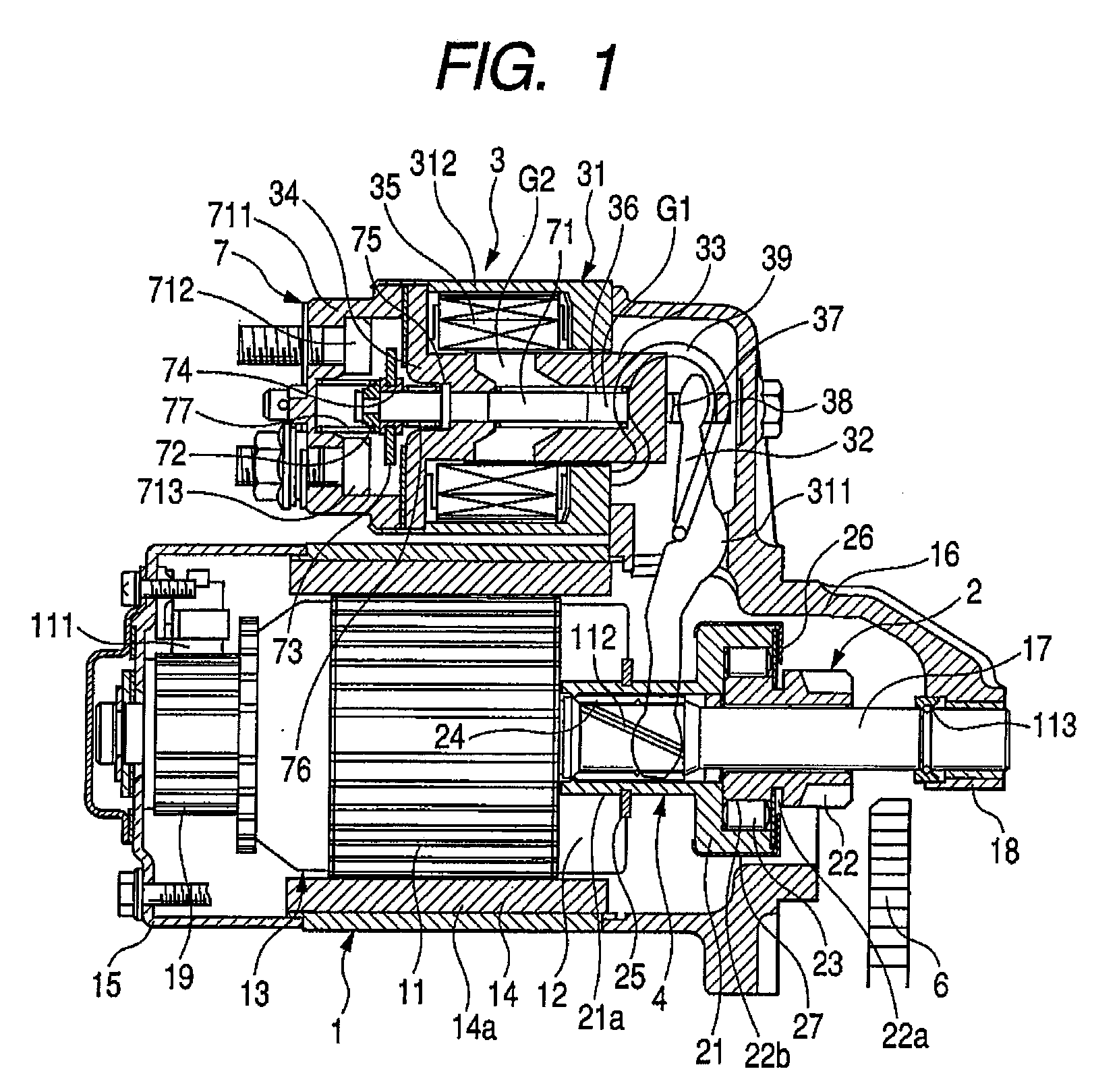
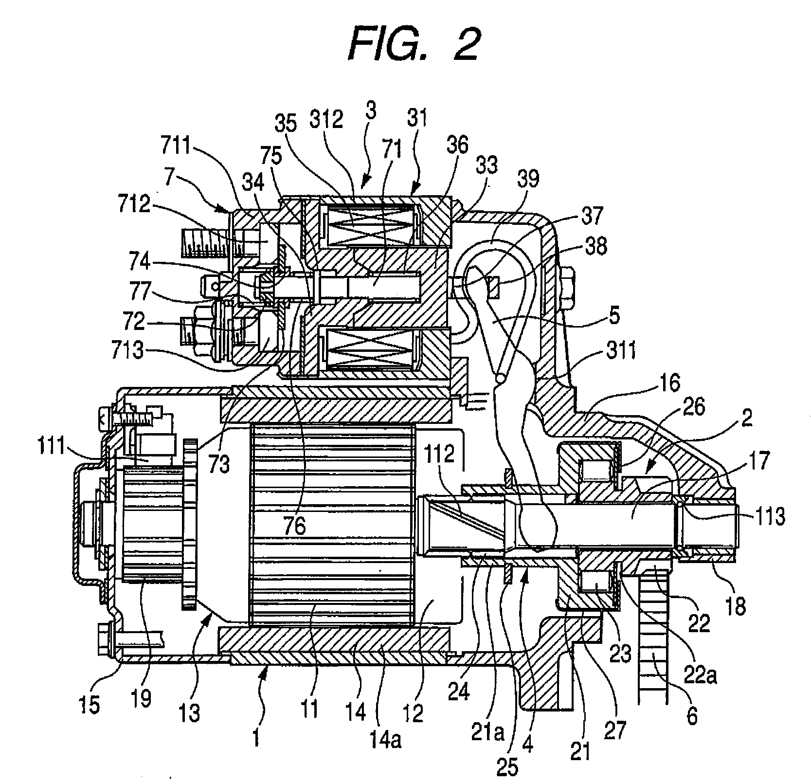
[0024]A starter of a first embodiment of the present invention will be described below with reference to FIGS. 1 to 8. FIG. 1 is a sectional side view of a starter in a state where the engine starts. FIG. 2 is a sectional side view of the starter immediately after the engine is stopped. FIG. 3 is a sectional side view of the starter after a lapse of a predetermined time since the engine stops. FIG. 4 is a diagram showing a circuit of the starter. FIG. 5 is an enlarged view of a torque transmission member. FIG. 6 is a cross section view taken along line A-A of FIG. 5. FIG. 7 is a control flowchart after the engine is stopped. FIG. 8 is a control flowchart when the engine restarts.

[0025]The starter shown in FIGS. 1 to 3 receives power supplied from a battery mounted on a vehicle and generates torque for starting the engine. The vehicle with the starter of this embodiment has an idle stop function. The idle stop function is to automatically stop the engine when the vehicle is stopped i...

second embodiment

[0098]A second embodiment of the present invention will now be described with reference to FIGS. 9 to 11. FIG. 9 is a diagram showing a starter circuit of the second embodiment. FIG. 10 is a control flowchart performed after the engine is stopped in the second embodiment. FIG. 11 is a control flowchart performed when the engine restarts in the second embodiment. Parts common to those of the first embodiment will be referred to by the same names and the same reference numerals.

[0099]In the second embodiment, the movable contact 73 of the magnetic switch 7 comes into contact with the battery-side fixed contact 712 and the electric motor-side fixed contact 713 by the solenoid 31 of the electromagnetic actuator 3, and the current is supplied from the battery B to the starter motor 1. Unlike the first embodiment, a resistor 79 is provided between the electric motor-side fixed contact 713 and the starter motor 1. The resistance value of the resistor 79 is set so that the starter motor 1 i...


PUM


Abstract

The present invention provides as tarter capable of keeping a state where a pinion and a ring gear maintain meshing with each other when an engine stops without providing a plunger stopper using a solenoid or the like. The state where the pinion and the ring gear maintain meshing with each other in the engine stop mode continues by movement resistance which occurs when a torque transmission member moves. Concretely, an inclination angle of a helical spline in a helical spline engagement part is set so that the above state continues. The helical spline engagement part is a part where a helical spline on the outer periphery of an output shaft of a starter motor and a helical spline on the inner periphery of the torque transmission member mesh with each. Consequently, the above state continues without a plunger stopper using a solenoid or the like.

Description

CLAIM OF PRIORITY[0001]The present application claims priority from Japanese application serial no. 2006-353645, filed on Dec. 28, 2006, the content of which is hereby incorporated by reference into this application.FIELD OF THE INVENTION[0002]The present invention relates to a starter for an internal combustion engine.BACKGROUND OF THE INVENTION[0003]In recent years, the number of vehicles with an automatic engine stop and start system (it's also so called as an idle stop system) is increasing. The system stops an internal combustion engine automatically to carry out an idle stop when an automobile is stopped and restarts the engine automatically when the automobile is restarted from the idle stop, in order to reduce exhaust gases of vehicles. In a vehicle with the idle stop function, the starter needs to be driven each time the engine is restarted. The starter needs to restart the engine with the following action: when passing current to a magnetic switch for connecting electrical...

Claims


Application Information

Patent Timeline
Patent Type & Authority Applications(United States)
IPC IPC(8): F02N11/00G06F19/00F02D45/00F02N11/08F02N15/00F02N15/02F02N15/06H01H50/54
CPCF02N11/04F02N11/0814F02N11/0855F02N2200/047F02N15/065F02N19/005F02N2019/008F02N11/087
Inventor ISHII, KOJINISHIDA, TATSUMI
Owner HITACHI ASTEMO LTD
Why Eureka
Try Eureka