Method for evaluating and optimizing performance of chiller system

a chiller system and optimization method technology, applied in the field of chiller systems, can solve the problems of increasing the cost of equipment, so as to improve the efficiency of chiller operation, improve power saving efficiency, and achieve effective power saving efficiency

Inactive Publication Date: 2008-07-03
IND TECH RES INST
View PDF7 Cites 37 Cited by
  • Summary
  • Abstract
  • Description
  • Claims
  • Application Information

AI Technical Summary

Benefits of technology

[0010]According to the present invention, the total system power consumption of the chiller system is evaluated, without changing the current chiller system, and thereby finding out the optimal operating setting. Therefore, the total system power consumption of the chiller system is controlled to improve the power-saving efficiency. Compared with the conventional art of a method for evaluating and controlling a single subsystem, the present invention achieves a more effective power-saving efficiency.

Problems solved by technology

Large amounts of electrical power are used by chillers of an air condition control system, and thus, how to improve the efficiency of the chillers becomes an important power-saving issue for being researched.
However, for those factories or buildings those have being built, since the numbers and locations of the chillers and the cooling towers are fixed, if the power-saving efficiency is intended to be enhanced through a re-designing process, the building must be reconstructed, and the factories or buildings cannot be used temporarily.
However, through this way, the temperatures at the specific positions are retrieved as system feedback parameters, and a single control parameter is used to adjust the specific subsystem, the operating setting of the subsystem must be switched frequently, and the power-saving benefit is still limited.
However, only the specific subsystem is evaluated and adjusted, and other subsystems may overload or excessively output, such that the operation of other subsystems causes additionally unnecessary power consumption, and thus, the practical power-saving benefit is reduced.

Method used


Image

  • Method for evaluating and optimizing performance of chiller system
  • Method for evaluating and optimizing performance of chiller system
  • Method for evaluating and optimizing performance of chiller system

Examples


Embodiment Construction

[0021]In order to make a further understanding of the objectives, constructions, features, and functions of the present invention, the detailed description is given below through the embodiments.

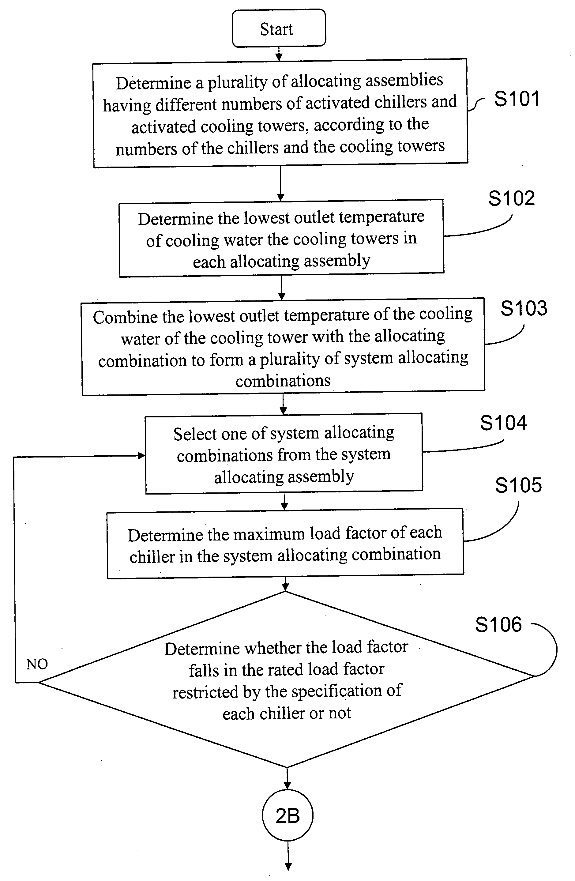
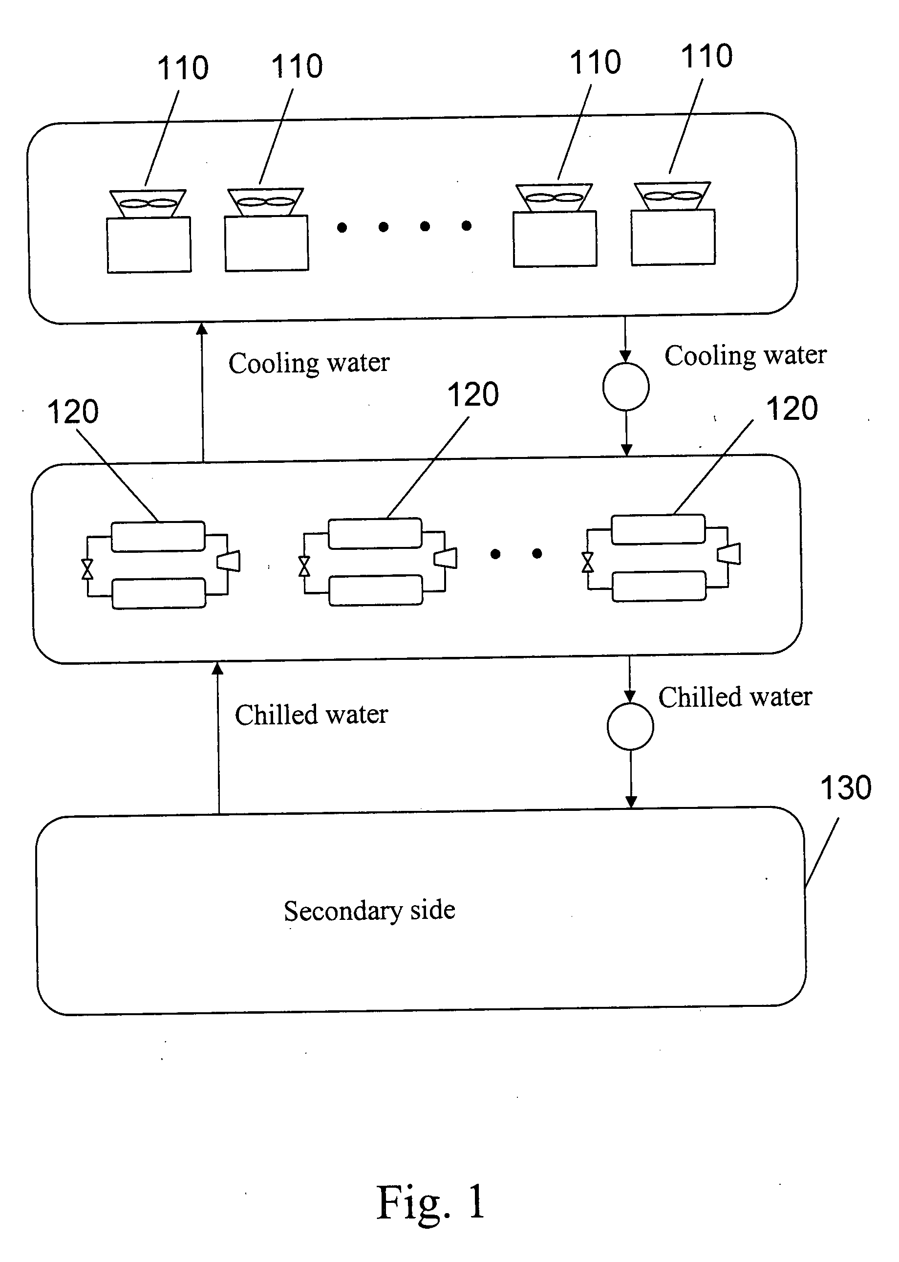
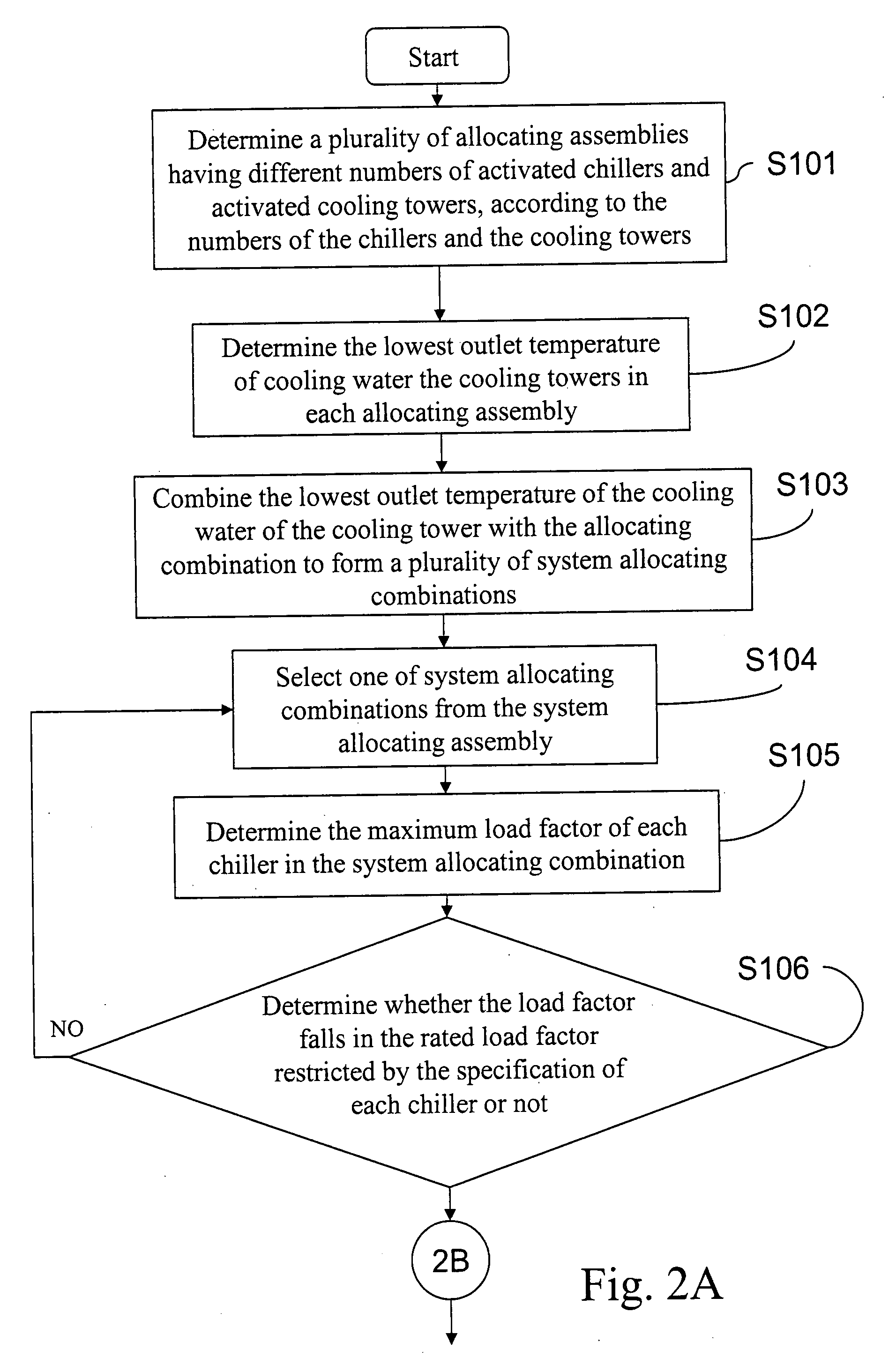
[0022]The present invention provides a method of evaluating and optimizing the performance of the chiller system, which is used to evaluate the total system power consumption of the chiller system under different settings of the number of the activated cooling towers, the number of the activated chillers, and the lowest outlet temperature of the cooling tower in an ambient temperature, so as to select the settings about the number of the activated cooling towers, the number of the activated chillers, and the lowest outlet temperature of the cooling tower capable of achieving the optimal power-saving efficiency from different total system power consumptions.

[0023]The numbers of the cooling towers and the chillers are determined as the chiller system is built, and the numbers of the activated ...


PUM


Abstract

A method of evaluating and optimizing performance of a chiller system includes the following steps. Determine a number of activated chillers, a number of activated cooling towers, and the lowest outlet temperature of cooling water of a cooling tower as an operating settings. By developing evaluating models, sequentially determine a temperature of the cooling water entering the chillers, a total power consumption of chillers, a total power consumption of the cooling towers, and a total power consumption of pumping cooling water. Then, determine a total power consumption of the system by the sum of the total power consumption of the chillers, the total power consumption of the cooling towers, and the total power consumption of pumping cooling water. Through the above method, the system total power consumptions under different operating settings are evaluated, so as to determine an optimized operating setting to optimize the performance of the system.

Description

CROSS-REFERENCE TO RELATED APPLICATIONS[0001]This non-provisional application claims priority under 35 U.S.C. §119(a) on Patent Application No(s). 095149328 filed in Taiwan, R.O.C. on Dec. 27, 2006, the entire contents of which are hereby incorporated by reference.BACKGROUND OF THE INVENTION[0002]1. Field of Invention[0003]The present invention relates to chiller systems. More particularly, the present invention relates to a method for optimizing a chiller system by evaluating performance of the chiller system, which is capable of evaluating power consumption of a chiller system through a number of activated chillers, a number of activated cooling towers, and a lowest outlet temperature of cooling water of cooling towers of the system.[0004]2. Related Art[0005]As for places those require air conditioning control, for example, air conditioned buildings, semiconductor factories, and cold storage warehouses, chiller systems are required to provide chilled water to chill the a in those ...

Claims


Application Information

Patent Timeline
Patent Type & Authority Applications(United States)
IPC IPC(8): G06F17/00
CPCF24F11/0009G06F2217/80G06F17/50F25B2400/06F24F11/30G06F2119/08G06F30/00F24F11/46F24F11/63F24F2140/00
Inventor CHANG, WEN-YAOWANG, TZXY-CHUIFU, WU-HSIUNGTZOU, MAN
Owner IND TECH RES INST
Why Eureka
Try Eureka