Room Arrangement, Ship, Building and Method for Constructing a Room Arrangement

a technology for building and room arrangement, which is applied in the direction of floating buildings, building components, hull panellings, etc., can solve the problems of occupying space, reducing the need reducing the need for cabin finishing work, so as to reduce the need for construction work at the shipyard, the effect of improving the quality and productivity of work

Active Publication Date: 2008-07-10
STX FINLAND OY +1
View PDF37 Cites 2 Cited by
  • Summary
  • Abstract
  • Description
  • Claims
  • Application Information

AI Technical Summary

Benefits of technology

[0029]One advantage of the invention is that the need for construction work at a shipyard is reduced. Thus, more and more cabin preparing work can be carried out in better conditions than in a shipyard, whereby the quality and productivity of work can be improved. At the same time, construction of a ship becomes faster and faster.
[0030]One advantage of the invention is that less cabin finishing work of the room units is needed at the installation location, for example cleaning. It is even possible to prepare a room arrangement with an interior made completely ready already at the factory. For example, a cabin module can be fabricated at a factory where its doors are locked after finishing and cleaning. The cabin module is transported to a shipyard, where it is installed into a ship totally from outside, and the doors will be opened only when all dirty installation work is finished.
[0031]One advantage of the invention is that a completely readily prefabricated room unit can be stored even outdoors and even in frosty weather because it is closed. It is possible to install heating into the room unit for the time of storage, or to use during storage a heating device that has possibly been installed into the room unit. This way the furniture and rugs, for example, of the room unit maintain in good condition.
[0032]One advantage of the invention is that due to the floor, the prefabricated room units can be more and more readily-made.
[0033]One advantage of the invention is that acoustic and refractory insulation of the room units according to the invention is easily made. Acoustic and thermal bridges are easily cut in both vertical and horizontal directions between each room units. A separating structure of class A according to the international Solas qualification in a ship can be achieved in horizontal level with the structures according to the invention. A fire classification of class E can be simply achieved for the buildings according to the invention.
[0034]Due to its layer structure, for example the walls, ceilings or floors of the spaces with structures of steel cellular boards can be built as fire separating whenever necessary. Thanks to the invention, fire compartmentation of buildings and vessels is thus facilitated or simplified.

Problems solved by technology

One drawback of the known prior art is, that a load-bearing base, onto which base the prefabricated room unit is installed, such as an intermediate deck of a ship or a floor structure of a building, is needed under each prefabricated room unit.
They also take space, and are extremely heavy structures.
Also load-bearing vertical structures, for example load-bearing walls and columns take space and increase the weight of a ship or a building.
The publication in question does not provide a solution for enabling connecting of more than two room units to each other in vertical direction so that the lower room units would sustain the gravity caused by the upper room units.
In order to solve the disadvantages of the prior art, solutions have been suggested, but it has not been possible to eliminate heavily structured ship decks, for example.
It is difficult to come up with a solution for acoustic and heat insulation of heavy hull structures, especially with strictly limited use of space.

Method used


Image

  • Room Arrangement, Ship, Building and Method for Constructing a Room Arrangement
  • Room Arrangement, Ship, Building and Method for Constructing a Room Arrangement
  • Room Arrangement, Ship, Building and Method for Constructing a Room Arrangement

Examples


Embodiment Construction

OF THE FIGURES

[0080]For the sake of clarity, some corresponding parts have the same reference numerals. Further for the sake of clarity, some dimensions in the figures are distorted.

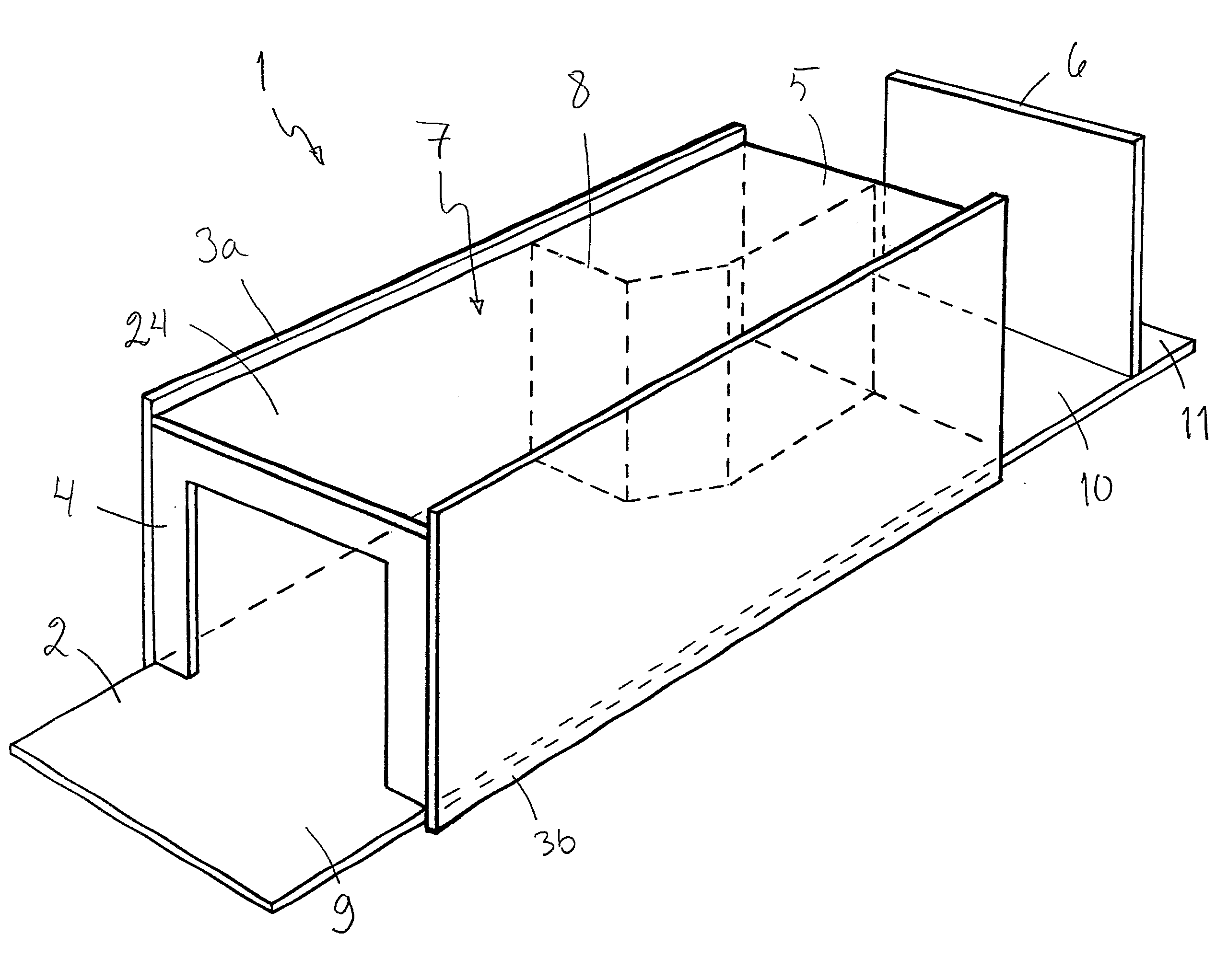
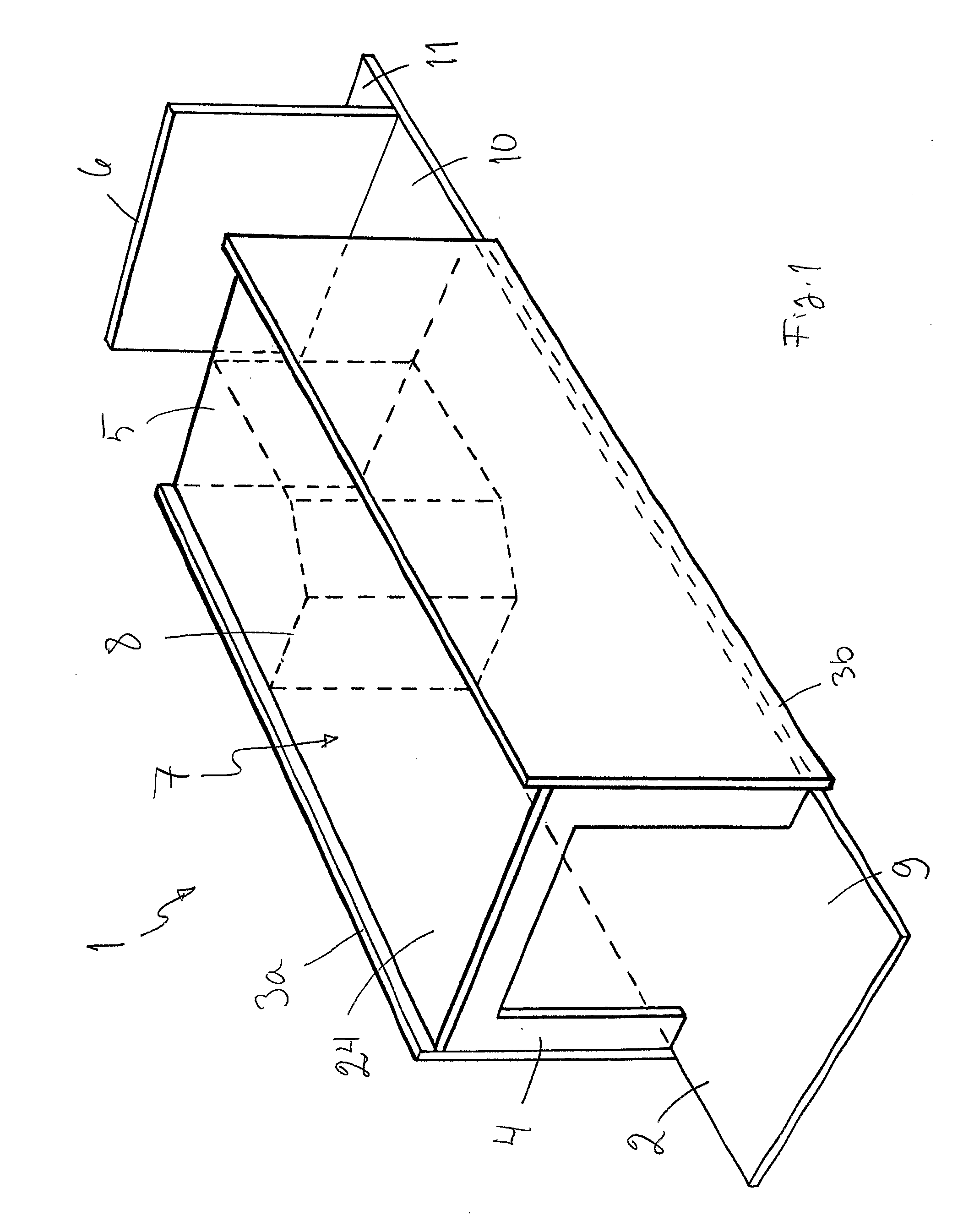
[0081]FIG. 1 shows a room unit 1 according to the invention. The room unit 1 has a floor plate 2, ceiling 24, sidewall panels 3a and 3b, outer wall panels 4, corridor wall panels 5 and another corridor wall panel 6, which are made of cellular board of steel. The wall panels 3, 4 and 5 and the ceiling 24 limit the space above the floor panel 2 to a room 7, such as a ship cabin. Inside the room, a bathroom 8 is shown in broken lines. The floor panel 2 extends to both sides of the outer wall 4 and the corridor walls 5 and 6. External parts of the floor of the room 7 form a balcony floor 9, corridor floor 10 and engineering and utility services room floor 11. The balcony floor 9 and the outer wall panel4 have been coated by stainless steel for improving their weather resistance. The floor 2 of the room unit ...


PUM


Abstract

Invention relates to a room arrangement (20) comprising at least two superposed prefabricated load-bearing room units have a ceiling (24), a floor (2) and at least two walls (3, 4, 5, 6) that are at least mainly of cellular board. The invention also related to a ship, building and method for constructing a room arrangement. The invention relates especially to a new manner of constructing multi-story rooms, for example, cabin compartments in ships or block of flats without middle decks or intermediate floors.

Description

TECHNICAL FIELD OF THE INVENTION[0001]The object of the invention is a room arrangement, ship, building and method for constructing a room arrangement according to the preambles of the independent claims presented below. The invention relates especially to a new manner of constructing multi-storey rooms, ship cabin compartments or block of flats, for example.PRIOR ART[0002]It is known to bring ship cabins as prefabricated cabin modules to a shipyard, where the cabin modules are installed into a ship. In ships, the cabin modules are installed on some load-bearing base, such as a bottom, intermediate decks or a main deck of the ship. Usually, there are no floors in the prefabricated cabins to be installed into ships, since the deck on which the cabin module is typically installed, forms a frame for the cabin floor. Even though room units are prefabricated, there are still various work phases to be completed at the installation location itself. Prefabricated room units can also be used...

Claims


Application Information

Patent Timeline
Patent Type & Authority Applications(United States)
IPC IPC(8): B63B29/02B63B3/68E04B1/348E04B2/74
CPCB63B29/025E04B2/7412E04B1/3483B63B2231/34E04B1/348
Inventor KORDELIN, TAPIO
Owner STX FINLAND OY
Why Eureka
Try Eureka