
Method of making a unit comprising a casing and diverging portion

a technology of diverging portion and casing, which is applied in the field of making a casing and diverging portion unit, can solve the problems of increasing the time and the cost of fabrication accordingly, high manufacturing cost, and difficulty in implementation, and achieve the effect of reducing the number of components and the number of operations required for making i

Active Publication Date: 2008-07-10
ARIANEGRP SAS
View PDF20 Cites 20 Cited by
  • Summary
  • Abstract
  • Description
  • Claims
  • Application Information

AI Technical Summary

Benefits of technology

[0010]The present invention seeks to remedy the drawbacks of prior art methods by proposing a method of making a casing-and-diverging-portion unit that enables the number of components and operations required for making it to be reduced.
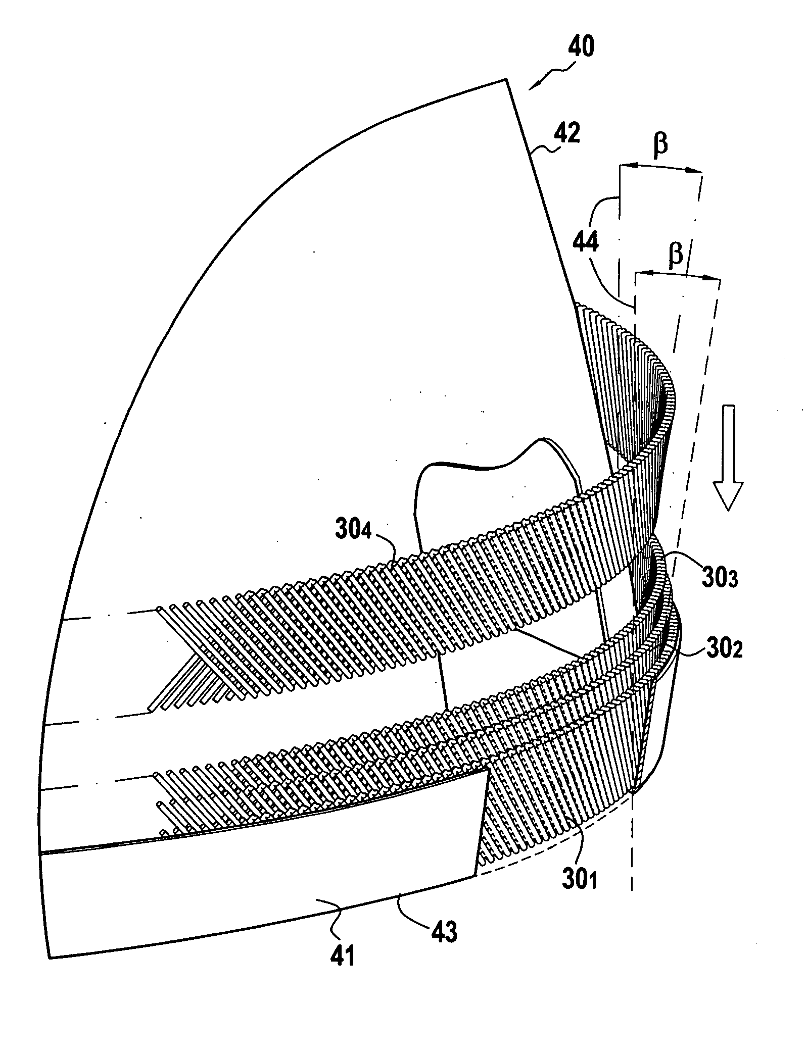
[0015]Thus, by making fiber reinforcement that combines the fiber preform for the diverging portion and the fiber preform for the casing, the method of the invention makes it possible to make a composite casing-and-diverging-portion unit with a minimum of operations. Once made, the fiber reinforcement is impregnated on a single occasion with a resin that, once polymerized, constitutes a matrix that is common both to the diverging portion and to the casing, so as to make both of those two structures within a single part. The number of operations needed for making the casing-and-diverging-portion unit is considerably reduced. In addition, by making common fiber reinforcement using two “dry” fiber preforms corresponding respectively to the diverging portion and to the casing portion, it is relatively easy to fit those two portions to each other since fiber preforms made of dry fibers lend themselves to being shaped.
[0016]Furthermore, reducing the number of components and operations required for making the casing-and-diverging-portion unit obtained by the method of the invention serves to reduce manufacturing costs considerably, in particular because it is possible to use single tooling for making the fiber reinforcement and single tooling for performing resin impregnation and polymerization using a single injection and polymerization cycle. With the method of the invention there is no need for any intermediate machining and adhesive bonding.
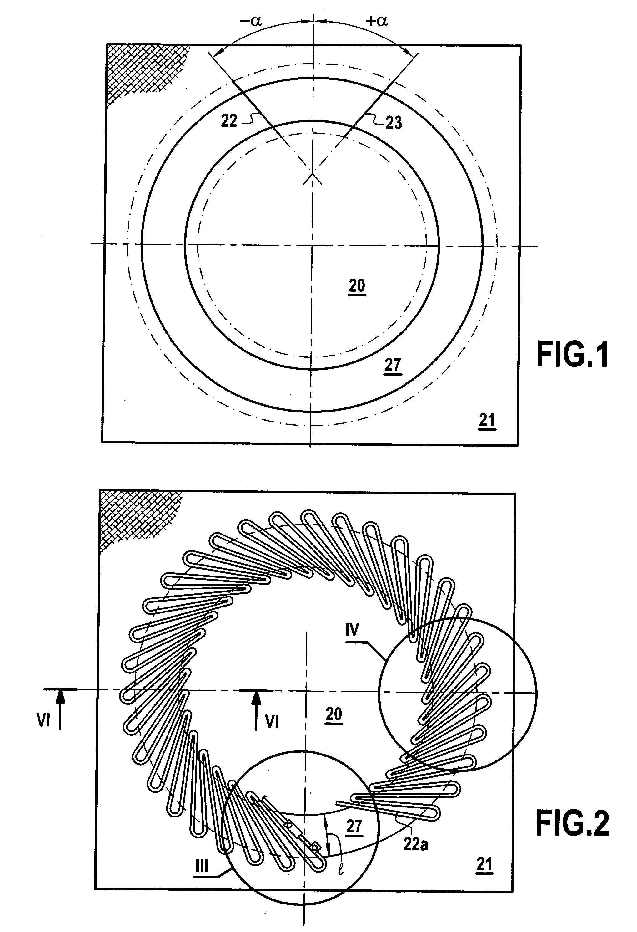
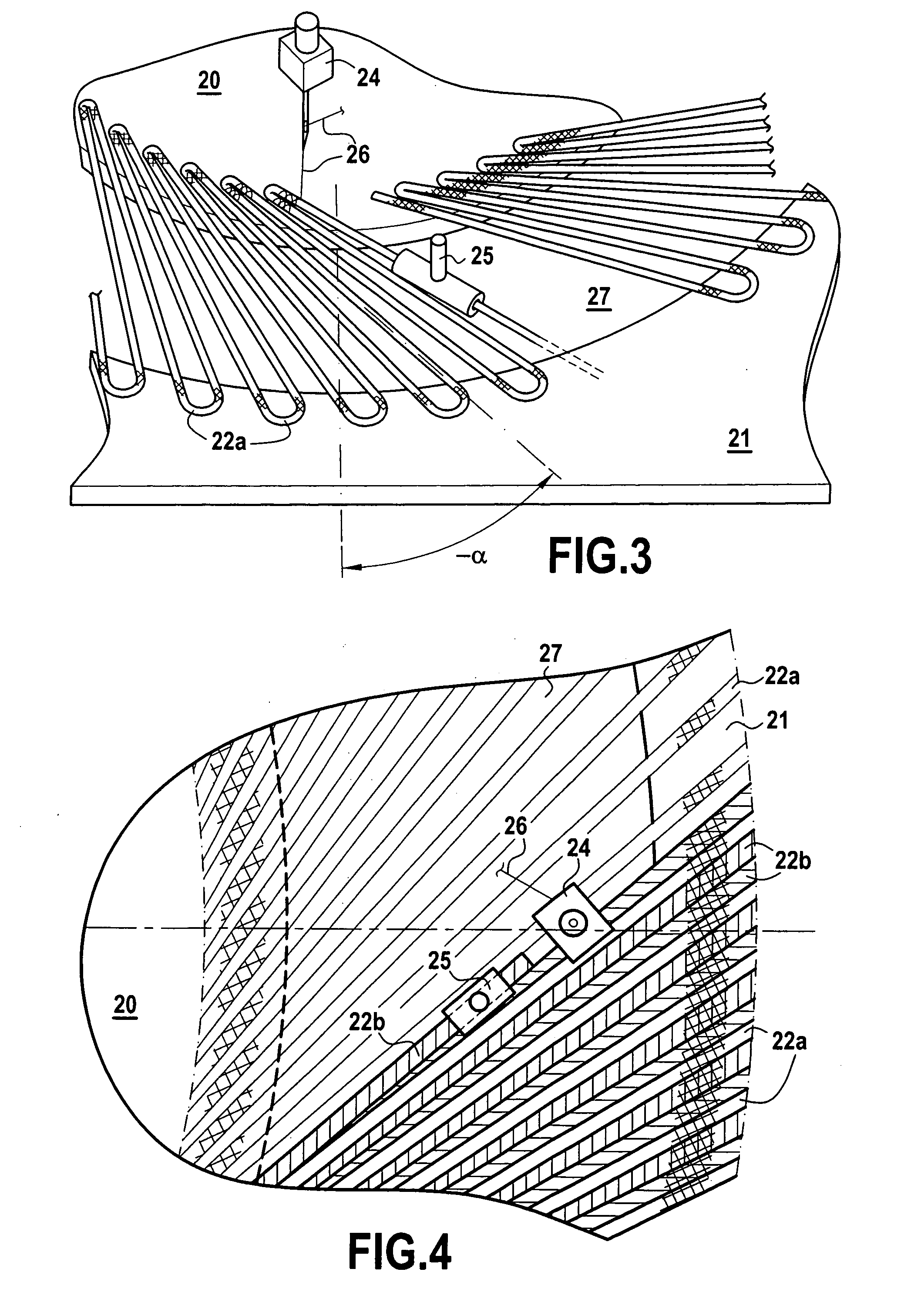
[0020]The first and second series of fibers in each annular fiber ply are made by automatically placing and stitching fibers between two canvases that define an annular space, each ply being removed from the canvases by being cut out after a circular connection has been made in said ply. In this way, the fiber plies for forming the preform of the diverging portion can be made flat between two canvases, thus making it possible to control accurately the orientation of the fibers. In addition, by using an automatic embroidery machine for placing the fibers between the two canvases, it is possible to automate fiber placement and to form fiber plies that are identical, in particular in terms of the orientations and quantities of fibers used.

Problems solved by technology

Nevertheless, with those methods of fabrication, the number of components needed for making the casing-and-diverging-portion unit is relatively large, as is the time required, thus leading to a manufacturing cost that is high.
Furthermore, since the diverging portion and the casing are made separately, assembling these two elements together can be complex and can present difficulties of implementation.
For example, aligning the contact surfaces between the casing and the diverging portion requires additional machining, thereby increasing the time and the cost of fabrication accordingly.
In addition, the above methods are difficult to implement.
In particular, draping fiber plies to form the fiber reinforcement is a manual operation that is performed directly on a shaping support and that does not enable accurate control to be maintained over the orientation and the quantity of fibers at all points in the reinforcement.
Furthermore, most existing methods use preimpregnated fibers that are less flexible than dry fibers, thereby making it even more difficult to shape the plies to match the shape of a body of revolution such as a diverging portion and the associated casing.

Method used


Image

  • Method of making a unit comprising a casing and diverging portion
  • Method of making a unit comprising a casing and diverging portion
  • Method of making a unit comprising a casing and diverging portion

Examples


Embodiment Construction

[0050]The present invention proposes a method of making a casing-and-diverging-portion unit that mainly comprises forming a fiber reinforcement from two types of fiber and impregnating the reinforcement with a resin to form a matrix. The fiber reinforcement is constituted by two fiber preforms corresponding respectively to the diverging portion and to the casing of the unit that is to be made.

[0051]The first preform, which is to form the fiber reinforcement corresponding to the diverging portion, is made with a first type of refractory fibers that present in particular low thermal conductivity, i.e. fibers presenting thermal conductivity of less than about 50 W·m−1·K−1, and preferably less than 20 W·m−1·K−1. By way of example, this first type of fiber may correspond to pitch-precursor, PAN-precursor, or rayon-precursor carbon fibers.

[0052]The second preform, which is to form the fiber reinforcement corresponding to the casing, is formed with a second type of fibers that present in p...


PUM

PropertyMeasurementUnit
Fractionaaaaaaaaaa
Pressureaaaaaaaaaa
Pressureaaaaaaaaaa

Abstract

The invention relates to a method of making a casing-and-diverging-portion unit, the method comprising the following steps:forming fiber reinforcement from a first fiber preform made with a first type of fiber and a second fiber preform made with a second type of fiber different from the first type of fiber, said second preform being placed on the first preform;maintaining the fiber reinforcement in tooling so that it has a shape identical to the shape of the casing-and-diverging-portion unit that is to be made; andimpregnating said fiber reinforcement with a thermosetting resin and impregnating the resin.

Description

BACKGROUND OF THE INVENTION[0001]The invention relates to making a casing-and-diverging-portion unit for use in particular in making components for rocket exhaust nozzles or outlet cones.[0002]That type of part comprises an internal portion referred to as the “diverging portion”, that is required essentially to present good ability at withstanding temperature and ablation since it is subjected directly to the flow of hot gas. The part also has an external portion, referred to as its “casing”, having the main function of imparting good stiffness to the part.[0003]Particularly because of the specific properties that the diverging portion and the casing need to present, these two portions are made separately. Thereafter they are united to form a casing-and-diverging-portion unit.[0004]A method presently in use for forming composite diverging portions or casings consists in draping and molding plies of carbon fabric preimpregnated with a resin, e.g. a phenolic resin. More precisely, the...

Claims


Application Information

Patent Timeline
IPC IPC(8): B29C65/54
CPCB29C70/222B29C70/226B29C70/345B29C70/382B29C70/462B29C70/48Y10T156/1074B29K2995/0015B29K2995/0017B29K2995/0082B29K2995/0087B29L2031/3097B29K2033/04
Inventor LALANDE, JOELLEBALLION, FREDERIC
Owner ARIANEGRP SAS
Learn More