Cooled turbine blade cast tip recess

a cooling turbine and tip recess technology, applied in the field of turbine blades, can solve the problems of reducing the structural integrity of the blade, the design of the internal cooling circuit has become more complex, and the above-described blades have drawbacks

Active Publication Date: 2008-07-10
HONEYWELL INT INC
View PDF11 Cites 50 Cited by
  • Summary
  • Abstract
  • Description
  • Claims
  • Application Information

AI Technical Summary

Problems solved by technology

Consequently, the blades are subjected to high heat and stress loadings which, over time, may reduce their structural integrity.
As engine operation temperatures have increased and internal cooling circuit designs have become more complex, some drawbacks to the above-described blades have arisen.
Consequently, the blade may not cool as intended when air leaks out of the holes.
As a result, the tip wall may be misshapen and the tip recess may be imprecisely formed.
To prevent this, costly precision locating strategies, such as repeated x-ray verification techniques could be employed; however these techniques would also increase blade manufacturing costs.

Method used


Image

  • Cooled turbine blade cast tip recess
  • Cooled turbine blade cast tip recess
  • Cooled turbine blade cast tip recess

Examples


Embodiment Construction

[0023]The following detailed description of the inventive subject matter is merely exemplary in nature and is not intended to limit the inventive subject matter or the application and uses of the inventive subject matter. Furthermore, there is no intention to be bound by any theory presented in the preceding background or the following detailed description.

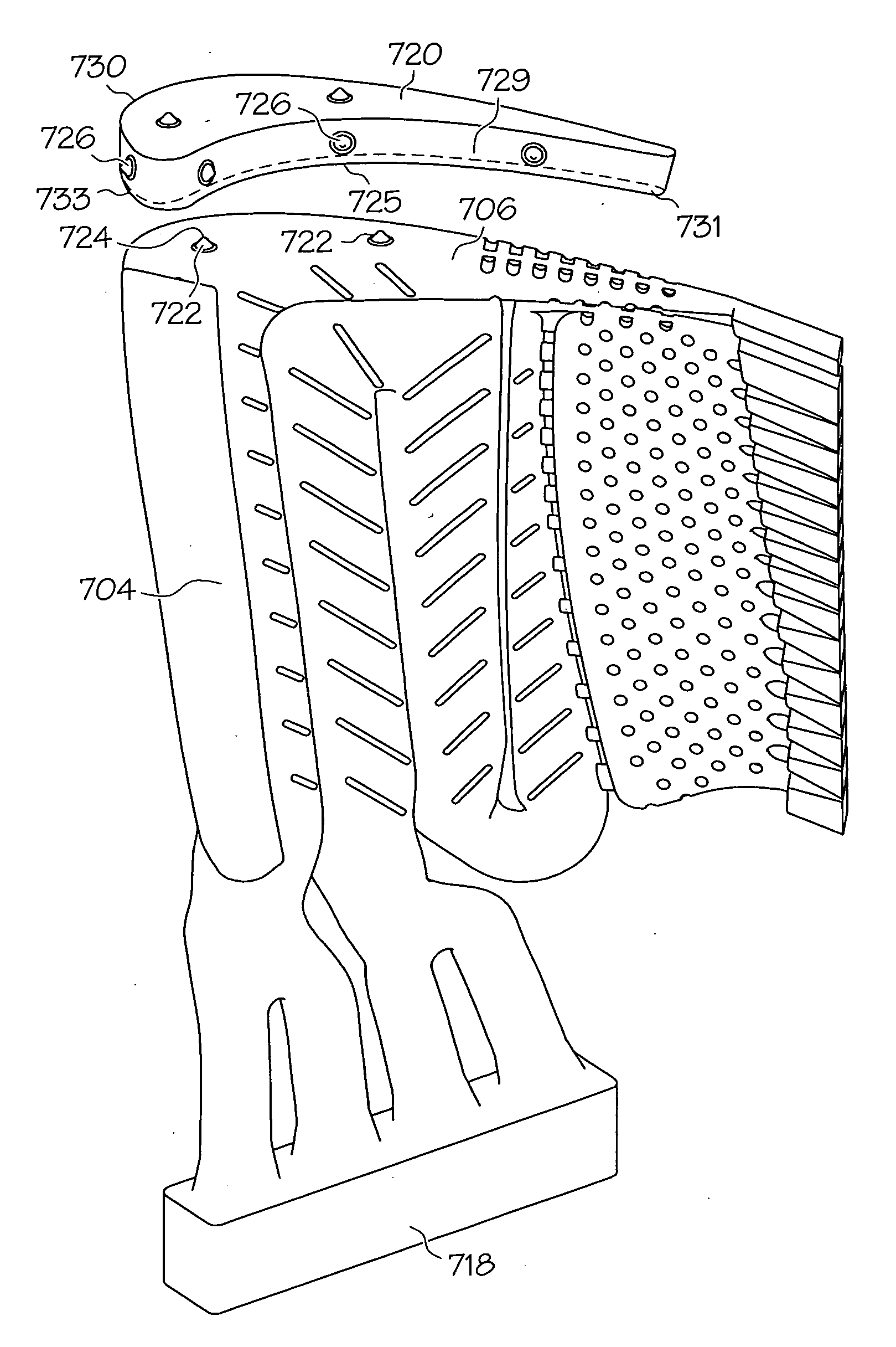
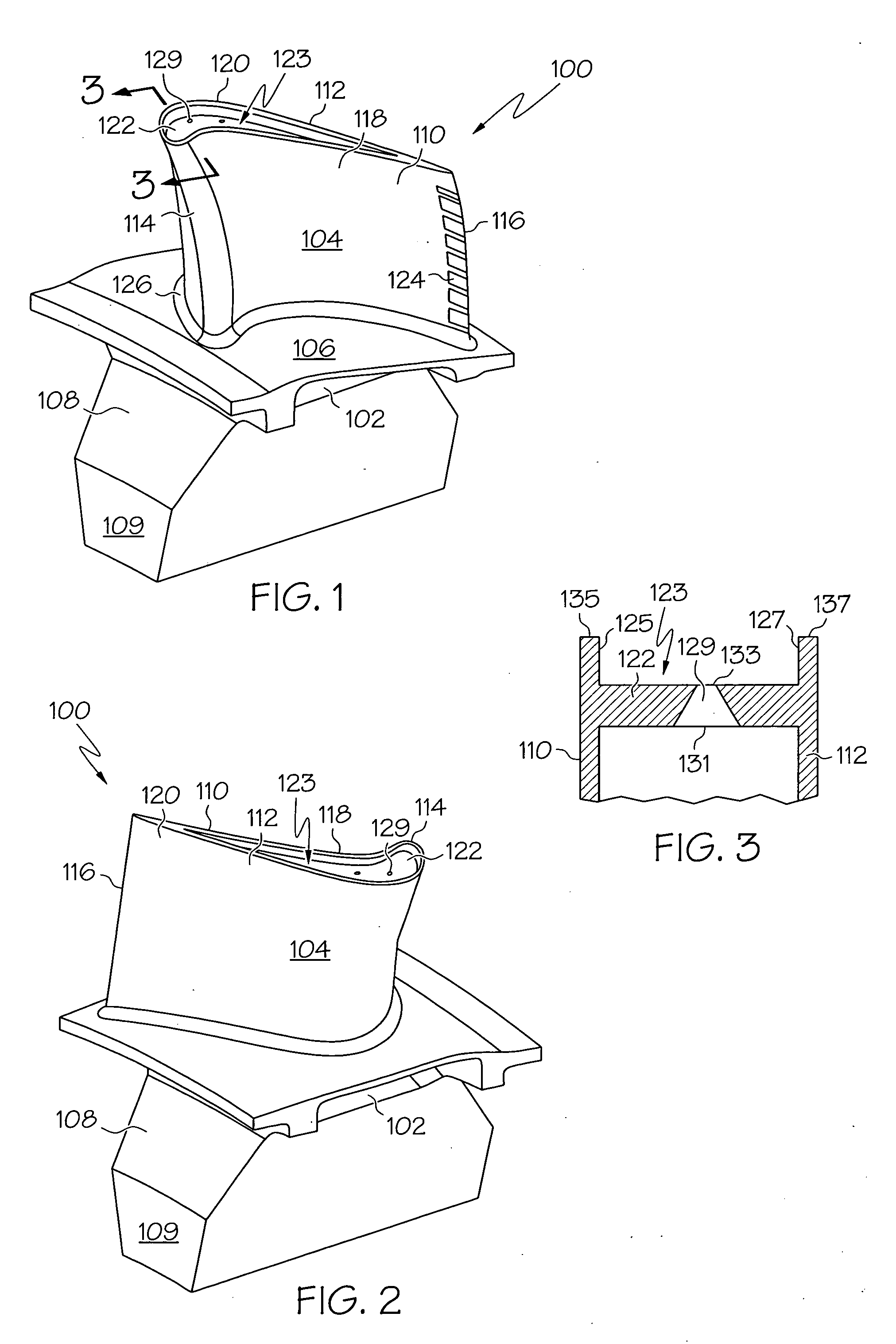
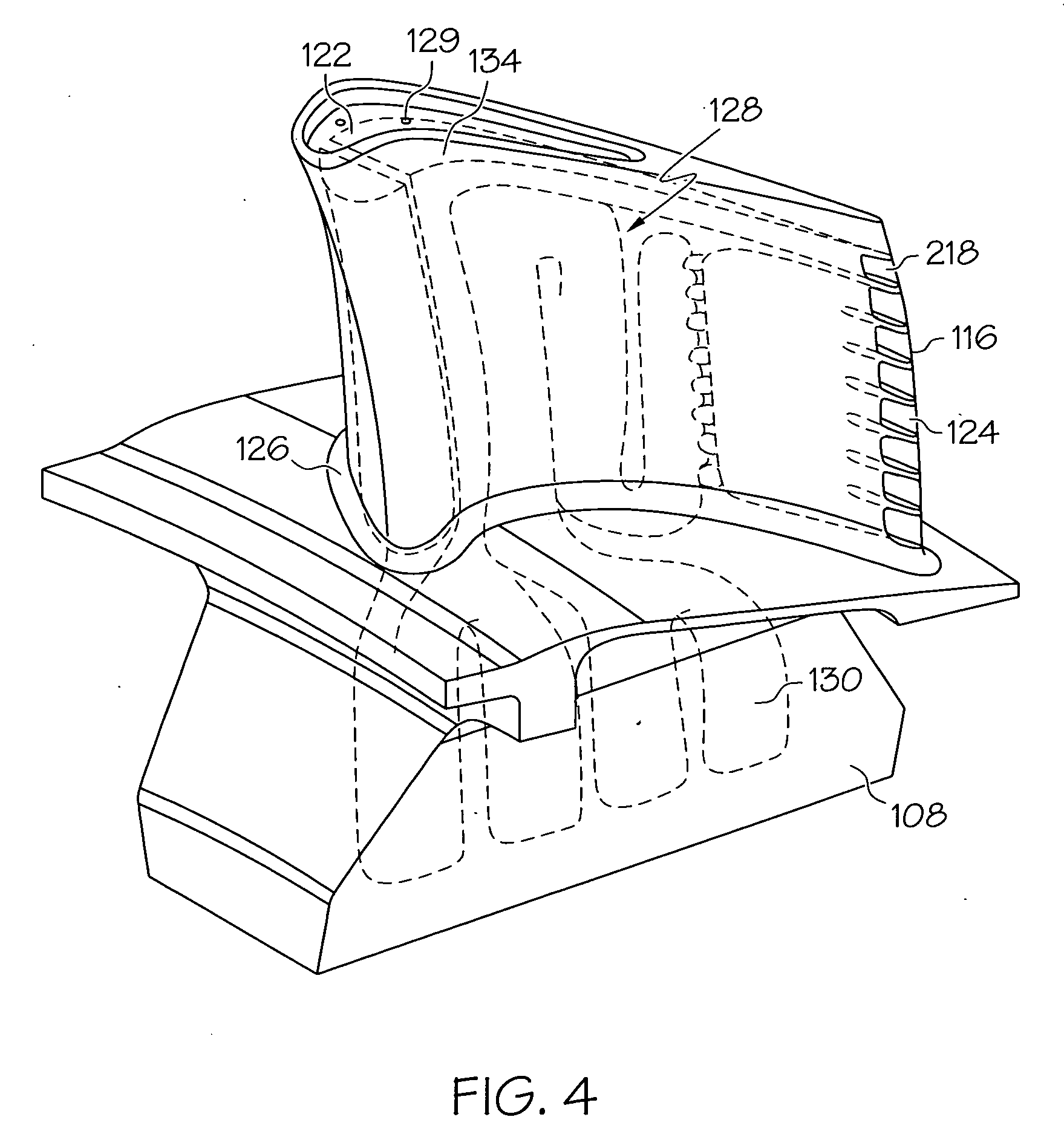
[0024]FIGS. 1 and 2 illustrate an exemplary aircraft jet engine turbine rotor blade 100 that includes a shank 102, an airfoil 104, a platform 106 and a root 108. The platform 106 is configured to radially contain turbine airflow. The root 108 provides an area in which a firtree 109 is machined. The firtree 109 is used to attach the blade 100 to a turbine rotor disc (not illustrated). It will be appreciated that in other embodiments, any one of numerous other shapes suitable for attaching the blade 100 to the turbine disk, may be alternatively machined therein. The airfoil 104 has a concave outer wall 110 and a convex outer wall 11...


PUM

PropertyMeasurementUnit
distanceaaaaaaaaaa
melting pointaaaaaaaaaa
heightaaaaaaaaaa

Abstract

A core assembly including two cores is used to manufacture a blade. The first core has an outer surface shaped to complement the tip wall bottom surface. The second core has a tip surface, a side surface, and a protrusion or a depression. The tip surface is shaped to complement at least a portion of the tip wall top surface and is configured to be disposed proximate the first core. The side surface is shaped to complement at least a portion of the side wall, and the protrusion extends from the second core side surface to contact at least a portion of the ceramic mold inner surface. In embodiments employing a depression, the depression is formed in the side surface.

Description

STATEMENT REGARDING FEDERALLY SPONSORED RESEARCH OR DEVELOPMENT[0001]This inventive subject matter was made with Government support under DAAJ02-94-C-0030 awarded by the United States Army. The Government has certain rights in this inventive subject matter.TECHNICAL FIELD[0002]The inventive subject matter relates to turbine blades and, more particularly, to casting tip recesses for high temperature cooled turbine blades.BACKGROUND[0003]Gas turbine engines, such as turbofan gas turbine engines, may be used to power various types of vehicles and systems, such as aircraft. Typically, these engines include turbines that rotate at a high speed when blades (or airfoils) extending therefrom are impinged by high-energy compressed air. Consequently, the blades are subjected to high heat and stress loadings which, over time, may reduce their structural integrity.[0004]To improve blade structural integrity, an internal cooling system is, in some cases, used to maintain the blade temperatures w...

Claims


Application Information

Patent Timeline
Patent Type & Authority Applications(United States)
IPC IPC(8): B22C9/10B22D7/06B22D29/00
CPCB22C9/04B22C21/14B22C9/103
Inventor MORRIS, MARK C.HALFMANN, STEVE H.SMOKE, JASON C.
Owner HONEYWELL INT INC
Why Eureka
Try Eureka