
Film Forming Apparatus

Active Publication Date: 2008-07-10
ULVAC INC
View PDF4 Cites 15 Cited by
  • Summary
  • Abstract
  • Description
  • Claims
  • Application Information

AI Technical Summary

Benefits of technology

[0019]According to the present invention, in the film forming chamber the pressure of which is controlled, while the cylindrical rotating body is rotated by the driving of the rotating body driving means, a film is formed on the top surface of the substrate on the substrate tray held on the substrate holder by using the first sputter film forming means, and also a film is formed on the back surface of the substrate on the substrate tray held on the substrate holder by using the second sputter film forming means.
[0023]Further, in the present invention, since the substrate tray is fixed by a magnetic force, even when the substrate tray is not rotated, the substrate tray can be prevented from coming off. Therefore, the substrate trays mounted on the cylindrical rotating body can be replaced one after another while the cylindrical rotating body is rotated stepwise.
[0026]Also, since the cylindrical rotating body is rotated around a substantially horizontal rotation axis, the substrate tray is transported horizontally, so that the construction can be simplified.
[0025]Further, in the present invention, since the electromagnet is used for mounting and demounting, the substrate tray can be mounted and demounted by the substrate mounting / demounting means.
[0026]Also, since the cylindrical rotating body is rotated around a substantially horizontal rotation axis, the substrate tray is transported horizontally, so that the construction can be simplified.

Problems solved by technology

However, it is difficult to provide a cooling means on the substrate because a film is formed on both surfaces of the substrate.

Method used


Image

  • Film Forming Apparatus
  • Film Forming Apparatus
  • Film Forming Apparatus

Examples


Embodiment Construction

[0050]The present invention will now be explained based on an embodiment shown in the drawings.

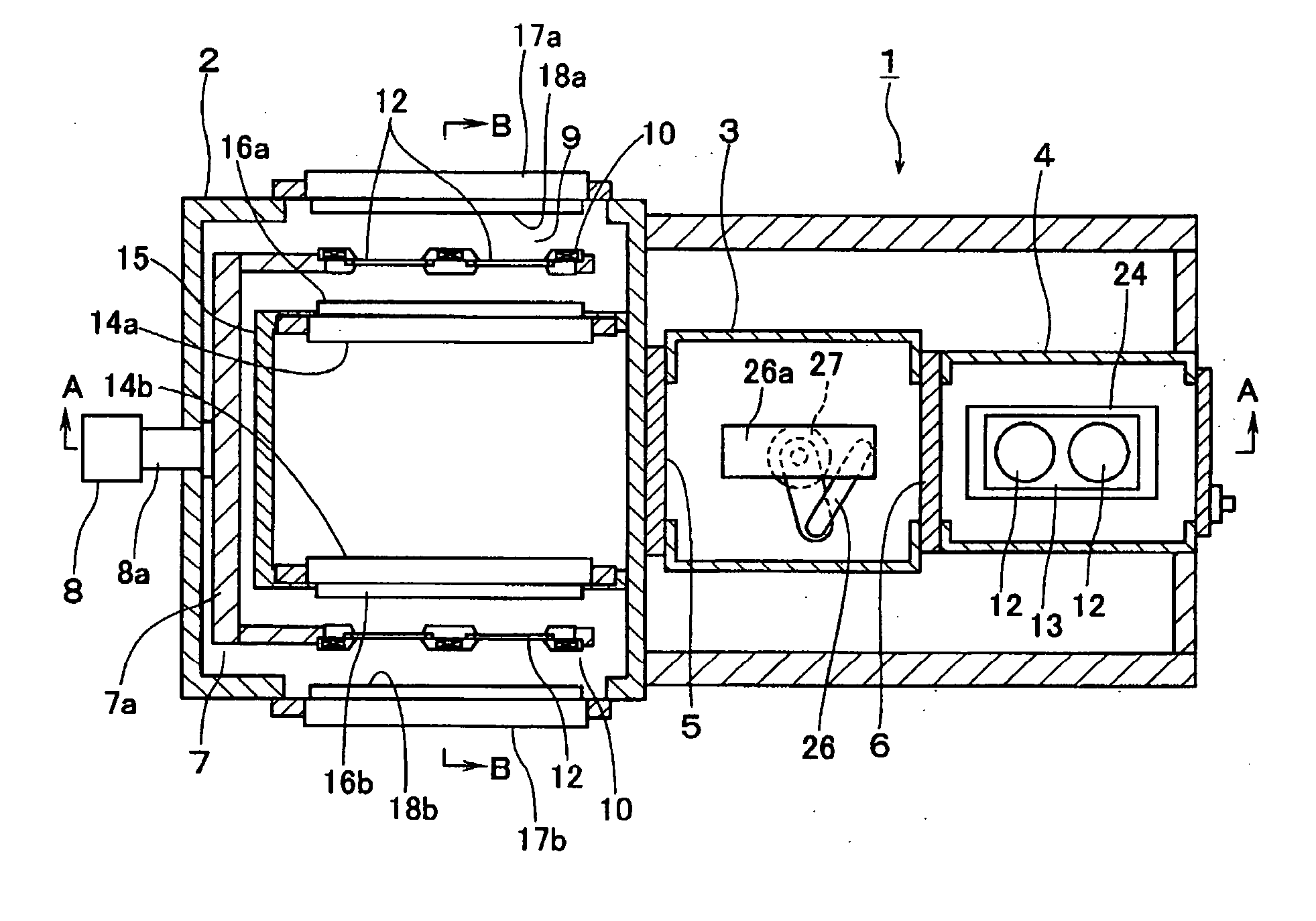
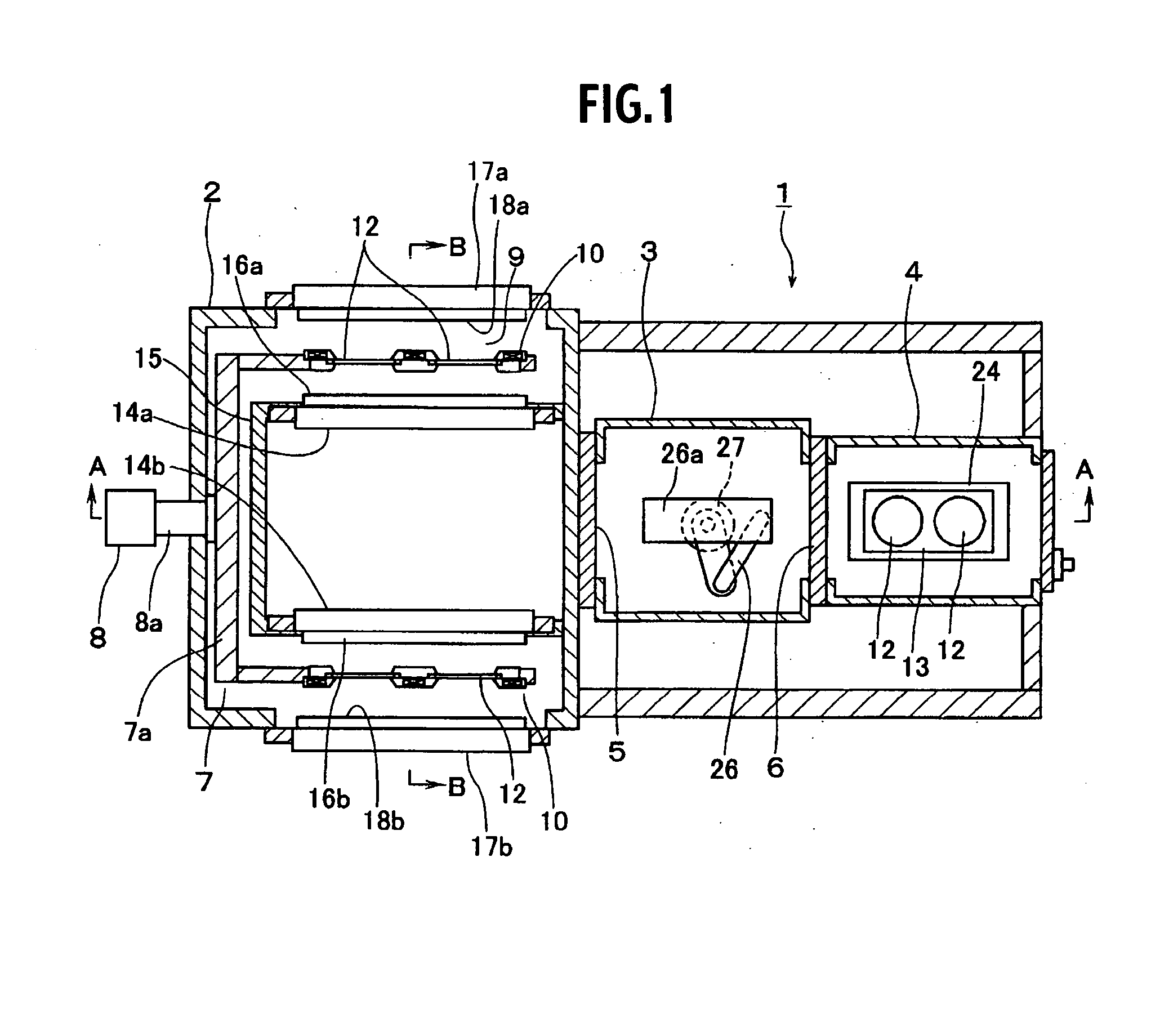
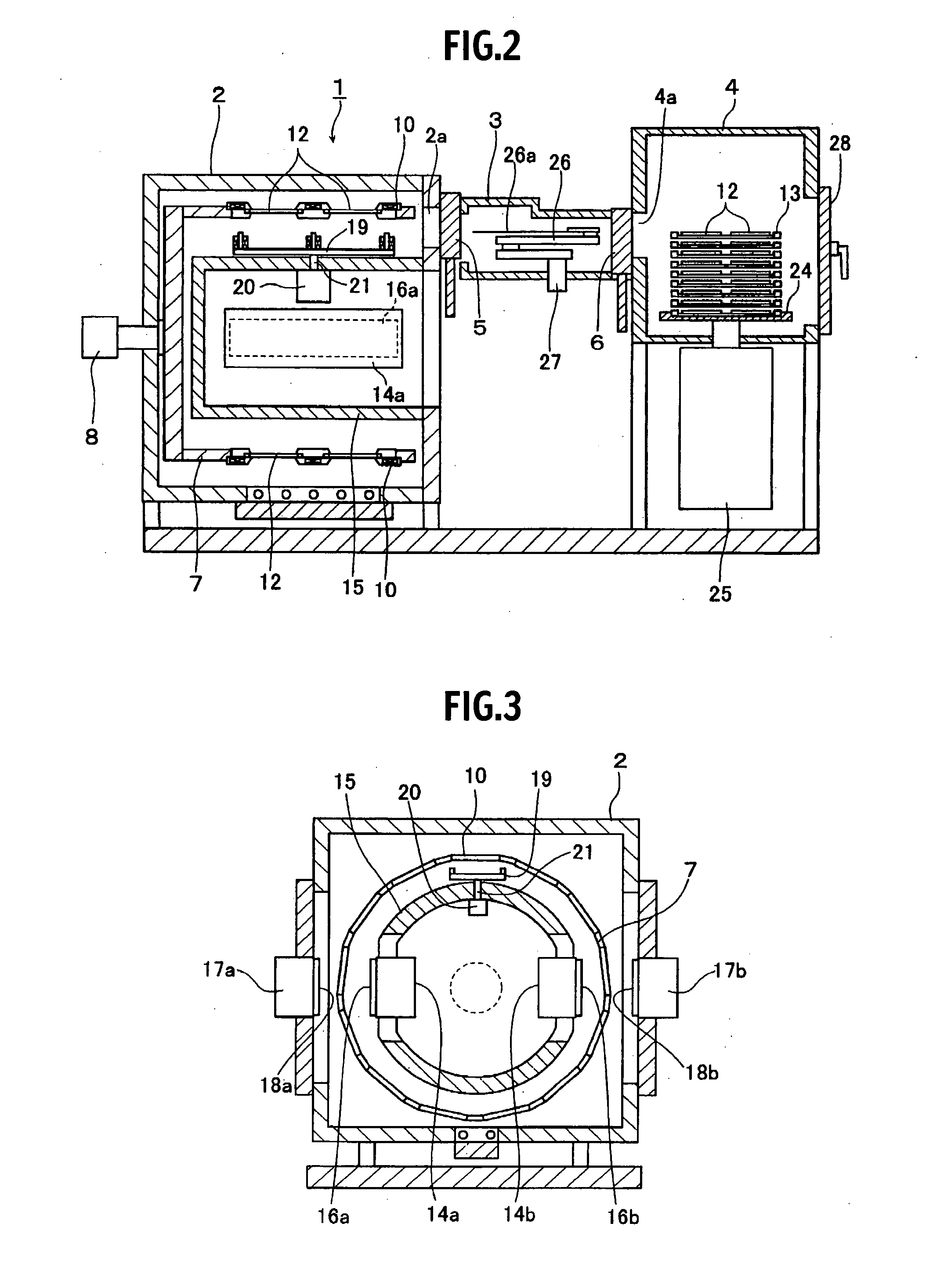
[0051]FIG. 1 is a schematic sectional view of a film forming apparatus in accordance with an embodiment of the present invention which carries out double-side film forming, viewed from the upper surface side, FIG. 2 is a sectional view taken along the line A-A of FIG. 1, and FIG. 3 is a sectional view taken along the line B-B of FIG. 1.

[0052]This film forming apparatus 1 is provided with a film forming chamber 2, a transportation chamber 3, and a feed / discharge chamber 4, and sluice valves 5 and 6 are provided between the film forming chamber 2 and the transportation chamber 3 and between the transportation chamber 3 and the feed / discharge chamber 4, respectively. In the film forming chamber 2, a rotating drum 7 having a substantially cylindrical outer peripheral surface is rotatably provided with the axis line direction thereof being horizontal. One side surface (the transportation chambe...


PUM

PropertyMeasurementUnit
Temperatureaaaaaaaaaa
Pressureaaaaaaaaaa
Magnetic forceaaaaaaaaaa

Abstract

There is provided a film forming apparatus which is capable of forming a film on both surfaces of a substrate by sputtering continuously with high efficiency by restraining a rise in temperature of the substrate to a predetermined value or higher.In a film forming chamber 2 the pressure of which is controlled, while a rotating drum 7 is rotated by the driving of a drive motor 8, a film is formed on the top surface of a substrate 12 on a substrate tray 13 held on a substrate holder 10 by cathodes 17a and 17b for outer surface to which a d.c. voltage or an a.c. voltage or a high-frequency voltage is applied, and also a film is formed on the back surface of the substrate 12 on the substrate tray 13 held on the substrate holder 10 by cathodes 14a and 14b for inner surface to which a d.c. voltage or an a.c. voltage or a high-frequency voltage is applied, by which a high-quality film is formed on both surfaces of the substrate 12 by sputtering continuously with high efficiency by restraining a rise in temperature of the substrate to a predetermined value or higher.

Description

TECHNICAL FIELD[0001]The present invention relates to a film forming apparatus. More particularly, it relates to a film forming apparatus in which a film is formed on both surfaces of a substrate by the sputtering technique.BACKGROUND ART[0002]In the case where a thin film is formed on a substrate, a sputtering system in which a thin film is formed on a substrate by the sputtering technique has conventionally been used. Generally, the sputtering system forms a thin film on one side of a substrate by the sputtering technique. However, a sputtering system in which targets are placed so as to face both surfaces of a substrate and a thin film is formed on both surfaces of substrate by the sputtering technique has also been proposed (for example, refer to Patent Document 1).Patent Document 1: Japanese Patent Laid-Open No. 5-295538[0003]In the conventional sputtering system (film forming apparatus) described in Patent Document 1, when a substrate subjected to double-side film forming is t...

Claims


Application Information

Patent Timeline
IPC IPC(8): C23C14/34
CPCC23C14/3464C23C14/505H01J37/34H01J37/32752C23C14/541C23C14/34
Inventor DOGI, MINORUODAGI, HIDEYUKISHIMADA, TETSUYAMATSUMOTO, MASAHIRO
Owner ULVAC INC
Features
  • Generate Ideas
  • Intellectual Property
  • Life Sciences
  • Materials
  • Tech Scout
  • Unparalleled Data Quality
  • Higher Quality Content
  • 60% Fewer Hallucinations
Learn More