Bicycle carrier

a bicycle frame and carrier technology, applied in the field of bicycle carriers, can solve the problems of dents or scratches, scratches, chipping or otherwise marring the finish of expensive bicycle frames, etc., and achieve the effect of reducing aerodynamic drag and increasing fuel economy

Active Publication Date: 2008-07-10
FARNEY MICHAEL KENT
View PDF15 Cites 60 Cited by
  • Summary
  • Abstract
  • Description
  • Claims
  • Application Information

AI Technical Summary

Benefits of technology

[0015]As stated above, the bicycle carrier of the present invention is secured to and supported by the trailer receiver hitch of a vehicle. In this way, the bicycle(s) supported on the bicycle carrier are positioned at the rear of the vehicle, thereby reducing the aerodynamic drag associated with the bicycle secured to the vehicle, as opposed to a rack or racks secured elsewhere such as on the roof of the vehicle or other such known locations, this results in increased fuel economy over other designs. In addition, the bicycle(s) are protected from bugs and other road debris.

Problems solved by technology

With regard to racks that mount to the frame of the bicycle, such mounting systems have been known to cause dents in frames as well as to scratch, chip or otherwise mar the finish of expensive bicycle frames.
Such dents or scratches are generally caused by hooks, clamps, or cables secured to the frame which, during transport, rub or otherwise damage the bicycle frame.
In addition, when the bicycle frame is mounted to the bicycle carrier, there is typically nothing to support the handlebars, forks and wheels such that the handlebars, forks, and front wheels are allowed to turn as a result of momentum and wind forces upon them.
Such movement has been known to damage expensive bicycle frames, handlebars, forks and wheels.
Typically, when bicycles are in use, and especially with regard to mountain bicycles, these front wheels and tires are dirty and are known to transfer that dirt to the interior of the vehicle.
However, known problems associated with wheel-mounted racks are that when multiple bicycles are secured thereon, the adjacent handlebars, pedal cranks, pedals and seats are known to contact one another.
During transport, vibration and friction has been known to cause damage to these adjacent bicycles.
An alternative is to separate and provide a greater distance between adjacent bicycles; however, this requires a longer bicycle carrier which is disfavored for maneuverability of and accessibility to the vehicle.

Method used


Image

  • Bicycle carrier
  • Bicycle carrier
  • Bicycle carrier

Examples


Embodiment Construction

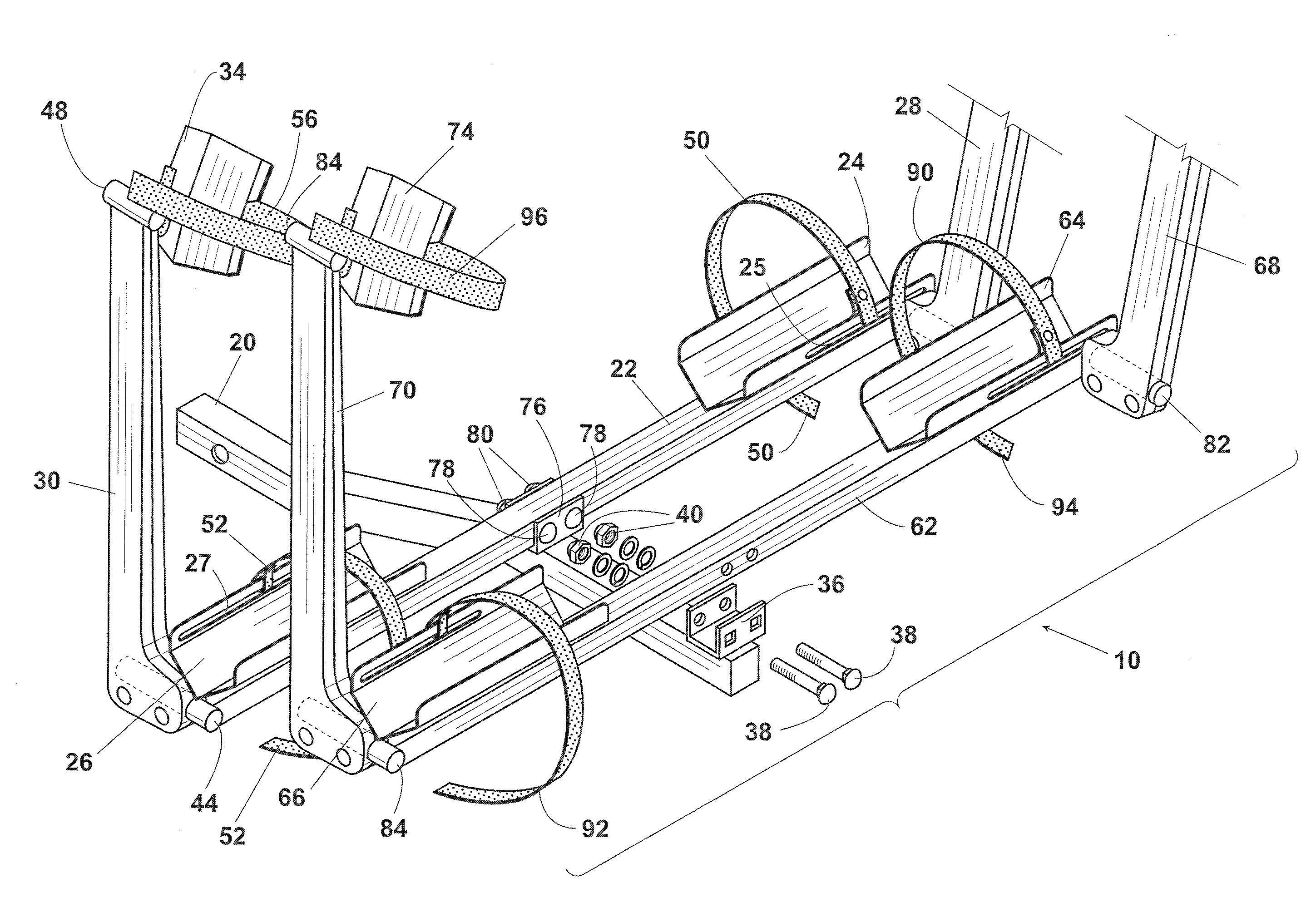
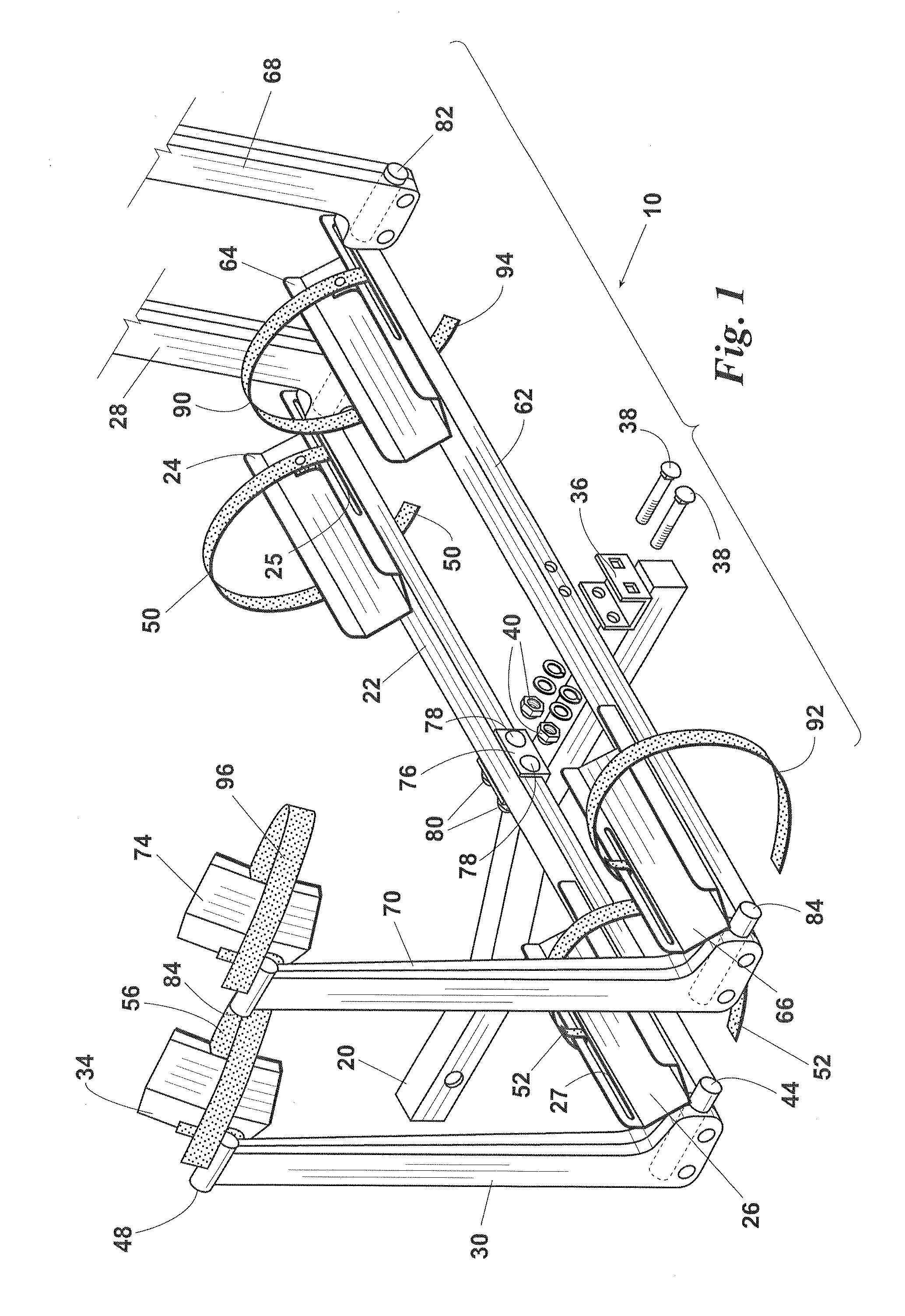
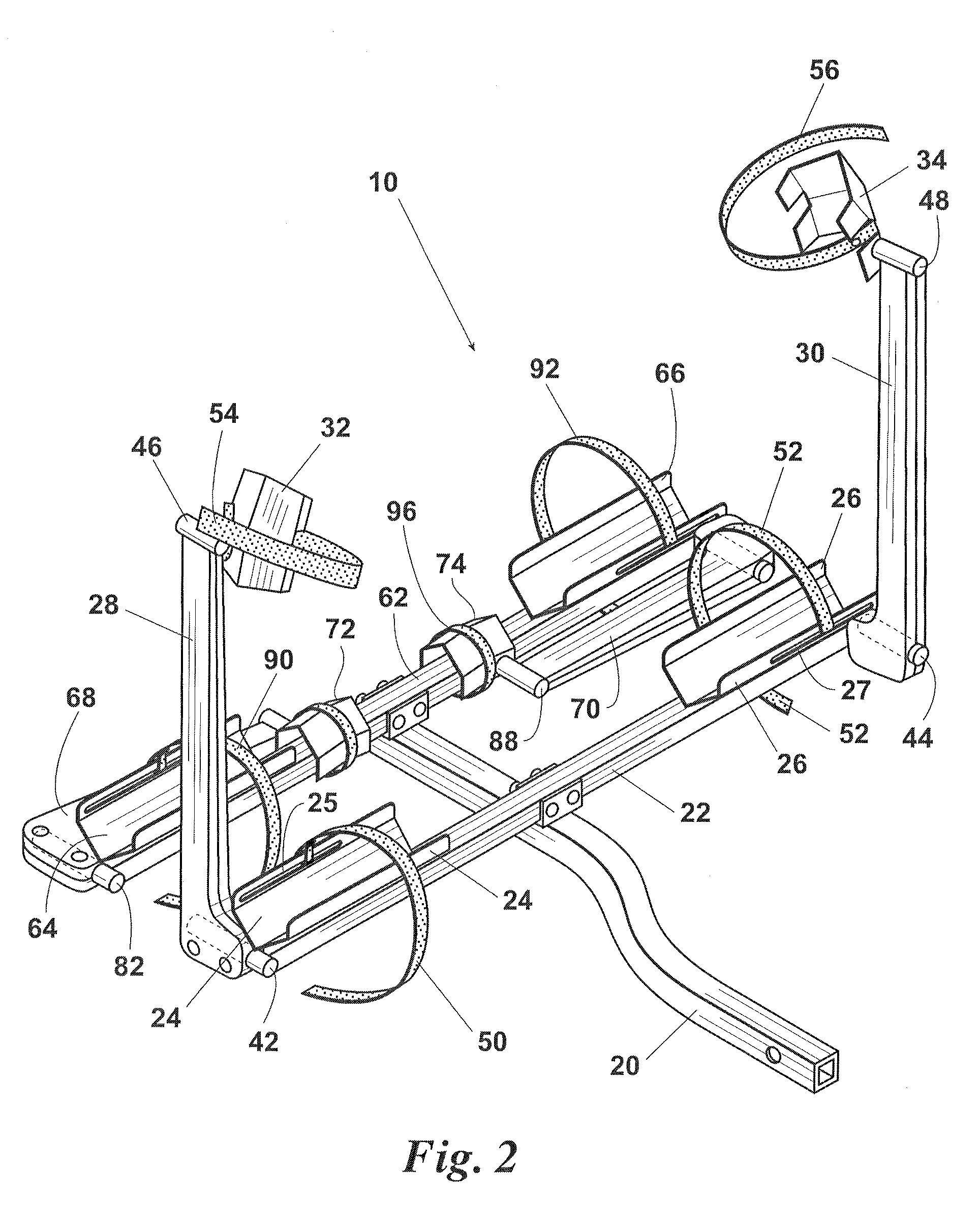
[0025]Referring to the FIGS., wherein FIG. 1 depicts bicycle carrier 10 of the present invention which includes generally a frame rail 20, a crossbar assembly 22, trays 24 and 26, swing arms 28 and 30 and shoe 32 and 34 (FIG. 2). In the preferred embodiment, as depicted in FIG. 1, two (2) wheel trays 24 and 26 are affixed to crossbar assembly 22. A plurality of wheeled trays such as 24 and 26 are preferred due a reduction in weight and material costs. However, it is understood that a single wheel tray could be employed of a length sufficient to receive both a front and a back wheel of a bicycle.

[0026]With reference to FIGS. 8 and 9, frame rail 20 includes a drawbar configured for insertion in a receiver 120 of a vehicle trailer hitch 122. Such trailer hitch receivers are known in the art and the frame rail 20 may be sized accordingly to fit the receiver 120. Crossbar assembly 22 is secured to a frame rail 20 through the use of a saddle 36 mounted to frame rail 20. Saddle 36 receives...


PUM


Abstract

A bicycle carrier for a vehicle including a frame, a crossbar assembly, a wheel tray, and a swing arm pivotally secured to the crossbar assembly. The wheels of the bicycle are positioned in the tray and secured by a tray coupling to restrain lateral movement. Two trays may be secured to the crossbar assembly to each receive a wheel of the bicycle. The swing arm pivots on the crossbar assembly and includes a shoe which engages the bicycle wheel. A shoe coupling secures the bicycle wheel to the swing arm. Two swing arms could be pivotally secured to the crossbar assembly each to engage a bicycle wheel. The frame may include a drawbar for insertion into the receiver of a trailer hitch. Additional crossbar assemblies could be secured to the frame to accommodate multiple bicycles.

Description

BACKGROUND OF THE INVENTION[0001]Conventional bicycle carriers for vehicles have included devices which are secured to the body of a vehicle, roof of a vehicle, or the trailer hitch of a vehicle. Such conventional bicycle carrier systems are known to attach either to the frame of the bicycle, the fork of the bicycle or the wheels of the bicycle.[0002]With regard to racks that mount to the frame of the bicycle, such mounting systems have been known to cause dents in frames as well as to scratch, chip or otherwise mar the finish of expensive bicycle frames. Such dents or scratches are generally caused by hooks, clamps, or cables secured to the frame which, during transport, rub or otherwise damage the bicycle frame. In addition, when the bicycle frame is mounted to the bicycle carrier, there is typically nothing to support the handlebars, forks and wheels such that the handlebars, forks, and front wheels are allowed to turn as a result of momentum and wind forces upon them. In additio...

Claims


Application Information

Patent Timeline
Patent Type & Authority Applications(United States)
IPC IPC(8): B60R9/10
CPCB60R9/10B60R9/06
Inventor FARNEY, MICHAEL KENT
Owner FARNEY MICHAEL KENT
Why Eureka
Try Eureka