Workholder for supporting electronic devices

a technology for supporting electronic devices and work holders, applied in the field of work, can solve the problems of reducing the effectiveness of adhesives, remaining adhesives on packages, and becoming a source of contamination for the rest of the manufacturing process, and achieve the effect of convenient manufacture and versatile us

Inactive Publication Date: 2008-07-10
ASM ASSEMBLY AUTOMATION LTD
View PDF12 Cites 9 Cited by
  • Summary
  • Abstract
  • Description
  • Claims
  • Application Information

AI Technical Summary

Benefits of technology

[0009]It is thus an object of the invention to seek to provide a workholder with a resilient holding surface for supporting electronic devices during singulation thereof that is easier to manufacture and more durable than some of the above prior art. It is a related object of the invention to seek to provide a holder for a workholder surface which is more versatile in use such that it can be used for multiple support purposes.

Problems solved by technology

However, as the dicing blade will come into contact with the adhesive tape during cutting, some adhesive will bond to the blade and reduce its effectiveness.
Another disadvantage of this process is that there may be adhesive still remaining on the package even after it is removed from the tape.
It may become a source of contaminant for the rest of the manufacturing processes.
It is difficult to fabricate as a lot of small pockets and small holes are made on the rubber sheet that is adhered onto a metal plate.
Hence, the manufacturing time and cost are high.
Moreover, it is unproductive when the whole jig or whole panel has to be re-done if just one pocket or hole is incorrectly made.
Although the rubber panel can be made by molding, some shrinkage of the molded part typically occurs during setting.
It is not easy to properly control such molding shrinkage problem.
Moreover, the cost of molding is comparatively high as one molded pattern for one type of substrate is not usable for other substrates with differently-positioned arrays.
The rubber commonly also has aging problems after it has been used for months and thus the positions of the pockets and holes may become misaligned.
However, the lip seals are not constructed according to the sizes of the packages so that it is more difficult to hold the packages securely after they are separated, and if the lip seals are cut into, they will have to be replaced, resulting in increased time and costs of replacement lip seals after each machining operation.
Furthermore, the lip seals are preferably formed integrally with an elastic mat, making it difficult to replace individual seals.
Although the disclosure briefly describes having discrete discs, these have to be glued onto a vacuum module with adhesive and have the problem that adhesive deteriorates over time.
If there are many small discs to be installed, it would also be time consuming to individually position and glue each disc, rather than just inserting them, which makes the approach less attractive.

Method used


Image

  • Workholder for supporting electronic devices
  • Workholder for supporting electronic devices
  • Workholder for supporting electronic devices

Examples


Embodiment Construction

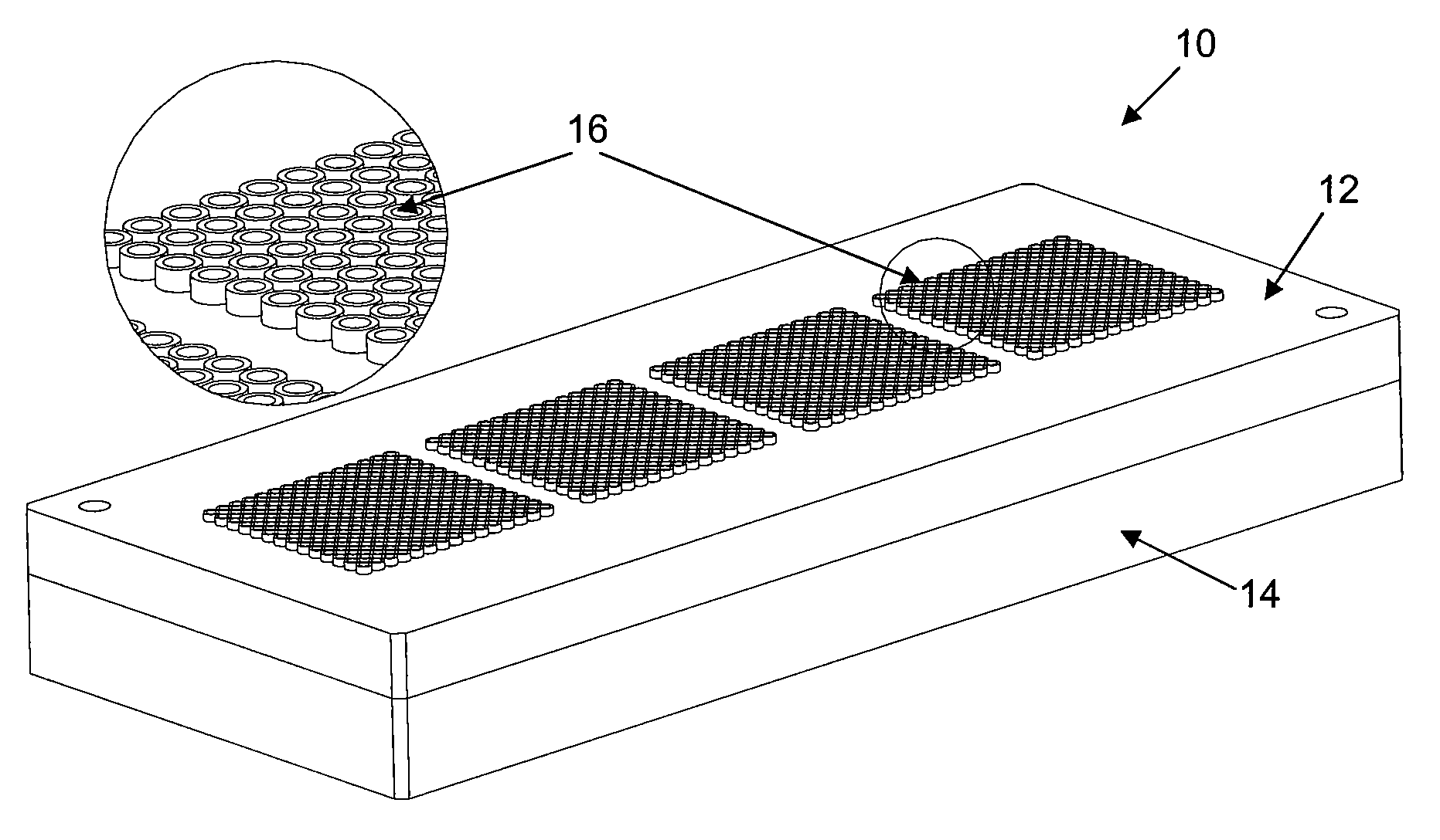
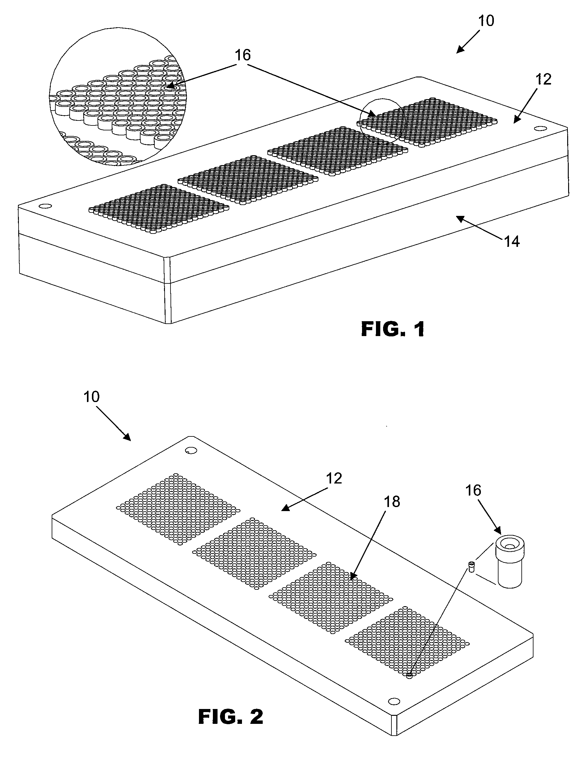
[0032]FIG. 1 is an isometric view of a saw jig 10 with individual round collets 16 according to the first preferred embodiment of the invention. The saw jig 10 is used for mounting a substrate (not shown) containing a plurality of electronic devices such as electronic packages, and comprises a base platform in the form of a saw jig base 12 and a base holder 14. A plurality of individual round collets 16 are arranged in an array pattern over the surface of the saw jig base 12 in the same positions as the arrangement of the individual electronic packages on the substrate to be cut. The saw jig 10 is connected to a vacuum source, such that vacuum suction can be generated at the holding surfaces at the top of the round collets 16. After the substrate is cut and the electronic packages are separated, each round collet 16 should preferably be of the appropriate size to be configured to hold one electronic package securely by vacuum suction.

[0033]The saw jig base 12 is preferably made from...


PUM


Abstract

A workholder, in particular a saw jig, is provided for mounting a substrate containing a plurality of electronic devices. The saw jig has a base platform having a plurality of pockets laid out in the same arrangement as the electronic devices are arranged on the substrate and a plurality of resilient collets are detachably inserted into the pockets, each collet being sized and configured to hold one electronic device by vacuum suction.

Description

FIELD OF THE INVENTION[0001]The invention relates to support structures or workholders such as saw jigs for holding electronic devices securely when processing the electronic devices, and in particular, to resilient holders located on the support structures for mounting said electronic devices.BACKGROUND AND PRIOR ART[0002]Conventionally, a number of electronic devices such as electronic packages are manufactured on a single strip of molded substrate comprising a plurality of such packages during semiconductor assembly and packaging, and it is necessary to separate them into singulated packages before offloading them. When singulating the electronic packages, for example, by using a dicing saw, it is usual to use a support structure such as an adhesive surface or vacuum chuck to hold the molded packages in place during the cutting process.[0003]Thus, one way of holding the substrate is by the use of a wafer frame and UV adhesive tape to secure the packages in place during the singul...

Claims


Application Information

Patent Timeline
Patent Type & Authority Applications(United States)
IPC IPC(8): B23Q3/02
CPCB25B11/005B23Q3/088B28D5/0094
Inventor CHENG, CHI WAHTSE, WANG LUNG ALAN
Owner ASM ASSEMBLY AUTOMATION LTD
Why Eureka
Try Eureka