Optical module

Inactive Publication Date: 2008-07-10
MEGAOPTO
View PDF0 Cites 11 Cited by
  • Summary
  • Abstract
  • Description
  • Claims
  • Application Information

AI Technical Summary

Benefits of technology

[0008]In order to overcome the above-mentioned problems, it is an object of the present invention to provide an optical module having a structure for protecting the pumping light source at a low cost.
[0010]In the optical module, the pumping light outputted from the pumping light source is subjected to a predetermined delay by the delay optical fiber, whereupon same is inputted through the first port of the optical coupler and is supplied to the amplification optical fiber via the common port of the optical coupler. However, the return light generated within the amplification optical fiber moves from the first port of the optical coupler to the pumping light source via the delay optical fiber, and is also outputted from the second port of the optical coupler, and thereby being detected by the photodetector. The control section controls the entry of the pumping light or seed light to the amplification optical fiber on the basis of the result of the detection result by the photodetector such that the entry of the return light to the pumping light source can be suppressed.
[0013]Thus, the delay, which is applied by the delay optical fiber to the pumping light outputted from the pumping light source, is longer than the time required from the light detection by the photodetector until the fluctuation in the output of the pumping light source. Hence, when the power of the light detected by the photodetector is greater than a predetermined value, the control section is able to stop the output of the pumping light from the pumping light source or reduce the intensity of the pumping light before the return light from the amplification optical fiber reaches the pumping light source (suppression of the entry of the return light to the pumping light source).
[0017]Thus, the delay that is applied by the delay optical fiber to the pumping light outputted from the pumping light source is longer than the time required from the light detection by the photodetector until the fluctuations in the output of the seed light source. Hence, when the power of the light detected by the photodetector is greater than a predetermined value, the entry of the return light to the pumping light source can be suppressed as a result of the control section stopping the output of the seed light from the seed light source or reducing the intensity of the seed light.
[0019]Thus, the delay, which is applied by the delay optical fiber to the pumping light outputted from the pumping light source, is longer than the time required from the light detection by the photodetector until the application voltage modulation of the seed light source is turned OFF. Hence, when the power of the light detected by the photodetector is greater than a predetermined value, the entry of the return light to the pumping light source can be suppressed as a result of the control section performing control to turn OFF the voltage modulation that is applied to the seed light source.

Problems solved by technology

The inventors have studied prior arts in detail, and as a result, have found problems as follows.
That is, in a conventional fiber laser light source, as a result of high-power light being generated within the amplification optical fiber, there are cases where light that propagates in the opposite direction from the normal light propagation direction such as reflected light caused by Rayleigh scatter within the amplification optical fiber and reflection by an optical device, and reflected light from the outgoing light also have a large amount of power.
However, a multi-mode optical isolator is rare and extremely costly.
Further, in a constitution in which a dielectric multilayered film filter or the like is inserted between the pumping light source and the amplification optical fiber, loss occurs in the high-power pumping light in the optical coupler and this is disadvantageous from the perspective of thermal radiation and the pumping efficiency.

Method used


Image

  • Optical module
  • Optical module
  • Optical module

Examples


first embodiment

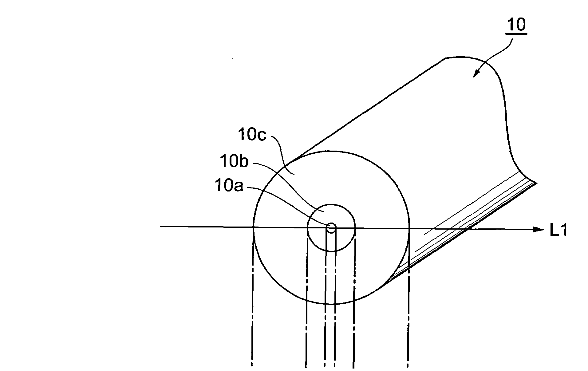
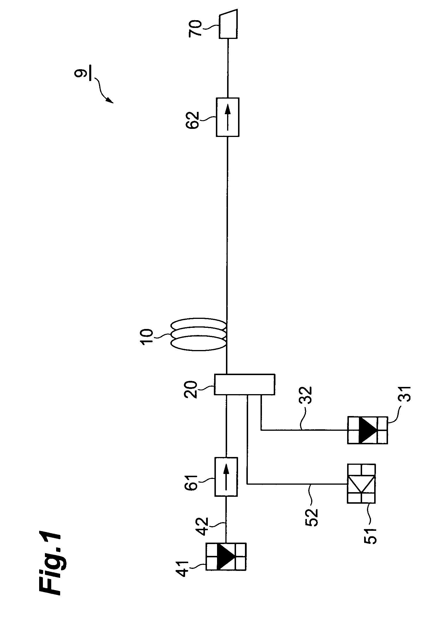
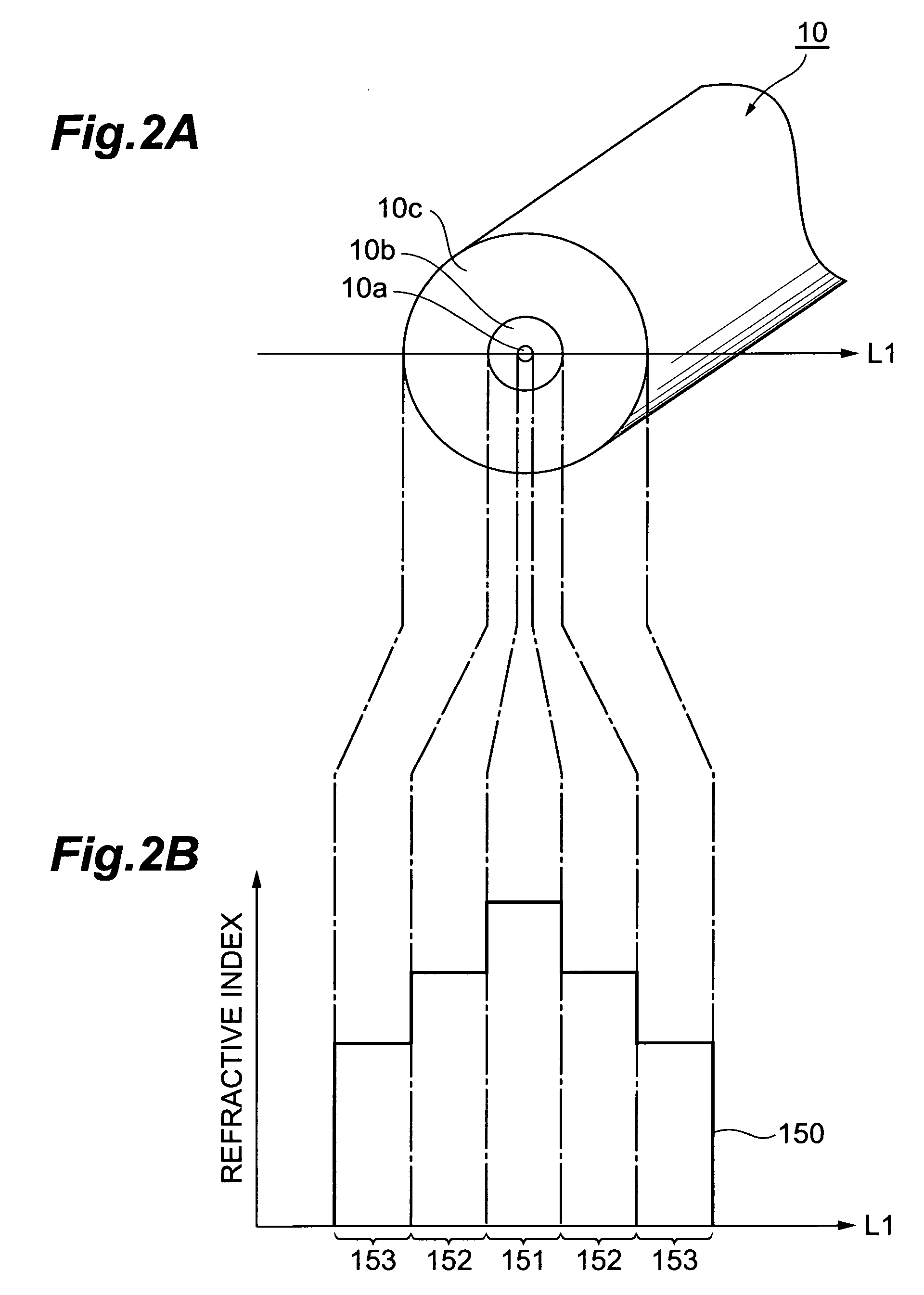
[0050]Subsequently, a first embodiment of the optical module according to the present invention will be described. FIG. 6 shows the constitution of the first embodiment of the optical module according to the present invention. The optical module 1 shown in FIG. 6 comprises an amplification optical fiber 10, an optical coupler 20, an pumping light source 31, a delay optical fiber 32, a seed light source 41, an optical fiber 42, a photodetector 51, an optical fiber 52, an optical isolator 61, an optical isolator 62, and a control section 91.

[0051]As compared with the constitution of the optical module 9 according to the comparative example shown in FIG. 1, the optical module 1 according to the first embodiment shown in FIG. 6 differs in that a delay optical fiber 300 having a desired length is provided between the pumping light source 31 and optical coupler 20. Further, the comparative example differs from the first embodiment also in that the comparative example comprises control sec...

second embodiment

[0059]Next, a second embodiment of the optical module according to the present invention will be described. FIG. 9 shows the constitution of the second embodiment of the optical module according to the present invention. The optical module 2 shown in FIG. 9 comprises an amplification optical fiber 10, an optical coupler 20, a pumping light source 31, a delay optical fiber 300, an optical device 33, a seed light source 41, an optical fiber 42, a photodetector 51, an optical fiber 52, an optical isolator 61, an optical isolator 62, and a control section 92.

[0060]In comparison with the constitution of the optical module 1 according to the first embodiment shown in FIG. 6, the optical module 2 according to the second embodiment shown in FIG. 9 differs in that the optical device 33 is provided between the pumping light source 31 and delay optical fiber 300. In addition, the second embodiment differs from the first embodiment in that the control section 92 is provided in place of the cont...

third embodiment

[0063]Next, a third embodiment of the optical module according to the present invention will be described. FIG. 10 shows the constitution of the third embodiment of the optical module according to the present invention. The optical module 3 shown in FIG. 10 comprises an amplification optical fiber 10, an optical coupler 20, a pumping light source 31, a delay optical fiber 300, a seed light source 41, an optical fiber 42, a photodetector 51, an optical fiber 52, an optical isolator 61, an optical isolator 62, and a control section 93.

[0064]In comparison with the constitution of the optical module 1 according to the first embodiment shown in FIG. 6, the optical module 3 according to the third embodiment shown in FIG. 10 differs in that the third embodiment comprises a control section 93 in place of the control section 91.

[0065]In accordance with the third embodiment, the control section 93 stops the output of the seed light source 41 which outputs seed light or reduces the intensity t...


PUM


Abstract

The present invention relates to an optical module that has a structure for protecting a pumping light source at a low cost. The optical module comprises an amplification optical fiber, an optical coupler, a pumping light source, a delay optical fiber, a seed light source, an optical fiber, a photodetector, an optical fiber, an optical isolator, an optical isolator, and a control section. Through the insertion of the delay optical fiber between the pumping light source and the optical coupler, the timing of the output control of the pumping light source which is carried out after the photodetector detects return light leads the timing with which the return light enters the pumping light source. Hence, the time with which the return light enters the pumping light source is shortened and the accumulative damage time of the pumping light source is reduced.

Description

CROSS-REFERENCE TO RELATED APPLICATION[0001]This application claims priority to Provisional Application Ser. No. 60 / 935812 filed on Aug. 31, 2007 by the same Applicant, which is hereby incorporated by reference in its entirety.BACKGROUND OF THE INVENTION[0002]1. Field of the Invention[0003]The present invention relates to an optical module comprising an amplification optical fiber that amplifies seed light by the supply of pumping light.[0004]2. Related Background Art[0005]Currently, processing technology that employs laser light is attracting attention and there is a greater need for a high-power laser light source in the fields of processing and medicine. Examples of laser light sources that have attracted particular attention among the various laser light sources include fiber laser light sources. In a fiber laser light source, an amplification optical fiber whose core is doped with Yb, Er, Tm or another rare earth element is adopted as the light amplification medium. When pumpin...

Claims


Application Information

Patent Timeline
IPC IPC(8): H01S3/067H01S3/10
CPCH01S3/06708H01S3/06754H01S3/0014H01S3/094011H01S3/10015H01S3/1301H01S3/13013
Inventor TAMAOKI, SHINOBU
Owner MEGAOPTO
Why Eureka
Try Eureka