Wireless Terminal Device

a terminal device and wireless technology, applied in substation equipment, resource management arrangements, selective content distribution, etc., can solve the problems of over-wireless communication devices, interference impairing noise margins, operating stability, and adjustment of devices, and it is difficult to reduce device siz

Active Publication Date: 2008-07-10
PANASONIC CORP
View PDF10 Cites 22 Cited by
  • Summary
  • Abstract
  • Description
  • Claims
  • Application Information

AI Technical Summary

Benefits of technology

[0012]To address the above problems, a first object of the present invention is to provide technology for avoiding problems caused by interference of two different local signals in a wireless terminal device. The wireless terminal device is for receiving a broadcast signal in which a plurality of programs are time-division multiplexed to reproduce a user-selected one of the programs as well as for receiving another radio signal to conduct predetermined processing.

Problems solved by technology

The above wireless communication device, however, has problems as follows.
With this structure, the two local signals interfere with each other, and the interference impairs the noise margin, operational stability, and adjustability of the device.
Further, there is another problem.
Provision of two sets of a local oscillator and a frequency converter for generating respective local signals makes it difficult to reduce the device size.
The problems noted herein are inevitable if the above structure is applied as it is to a wireless communication device for handling, for example, the DVB-T service and radio communication service.

Method used


Image

  • Wireless Terminal Device
  • Wireless Terminal Device
  • Wireless Terminal Device

Examples


embodiment 1

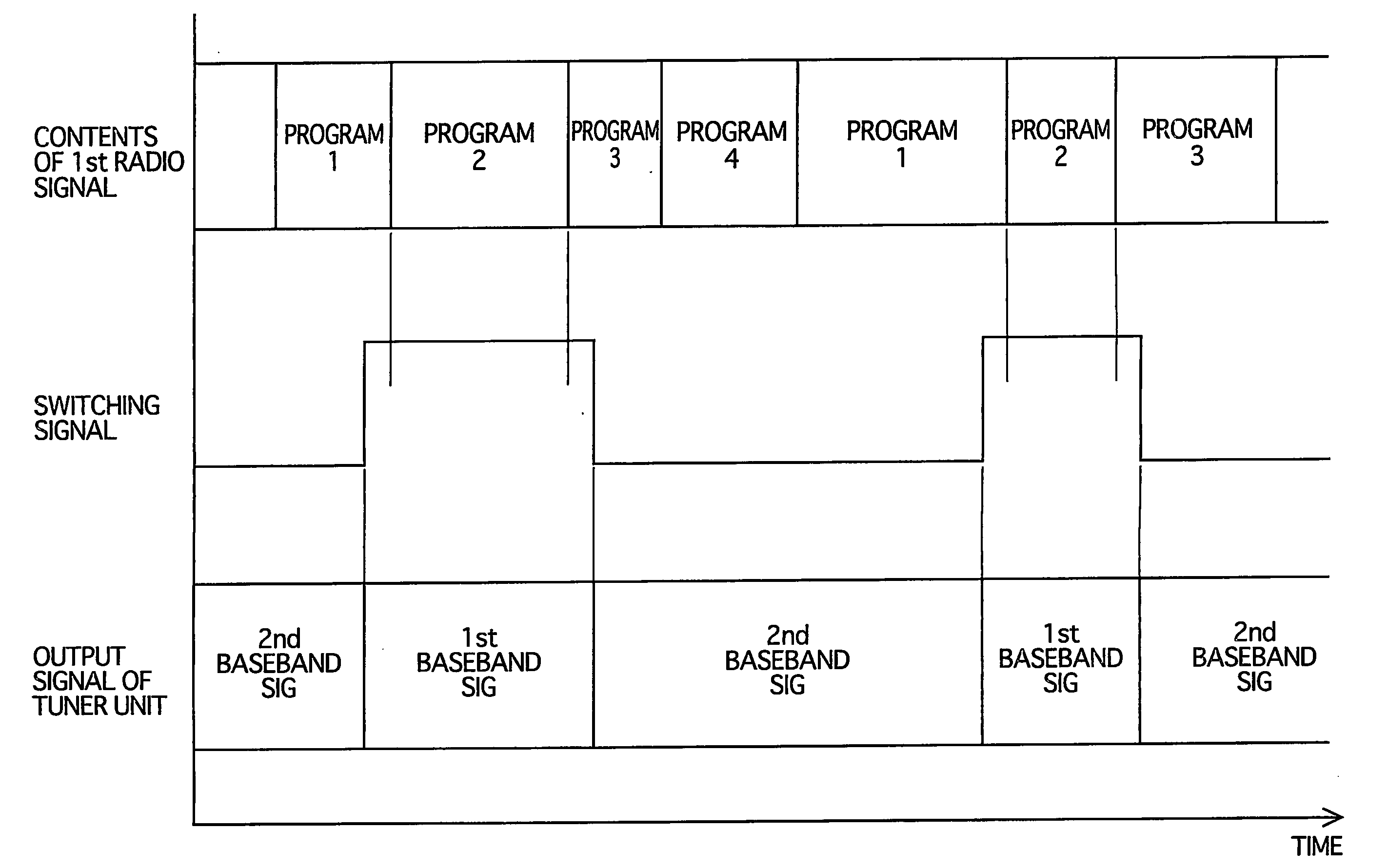
[0048]A wireless terminal device according to an embodiment 1 of the present invention receives a first radio signal relating to a first service which is a broadcasting service, and a second radio signal relating to a second service which is a position measuring service. The first radio signal represents a plurality of time-division multiplexed broadcast programs as well as periods during which the respective programs are represented. In addition to the reception of the signals, the wireless terminal device reproduces one of the programs selected by a user, and also measures its own current position based on the second radio signal.

[0049]The wireless terminal device of this embodiment may be implemented as a portable television receiver, a notebook personal computer, a mobile phone, or a PDA.

(Overall Structure)

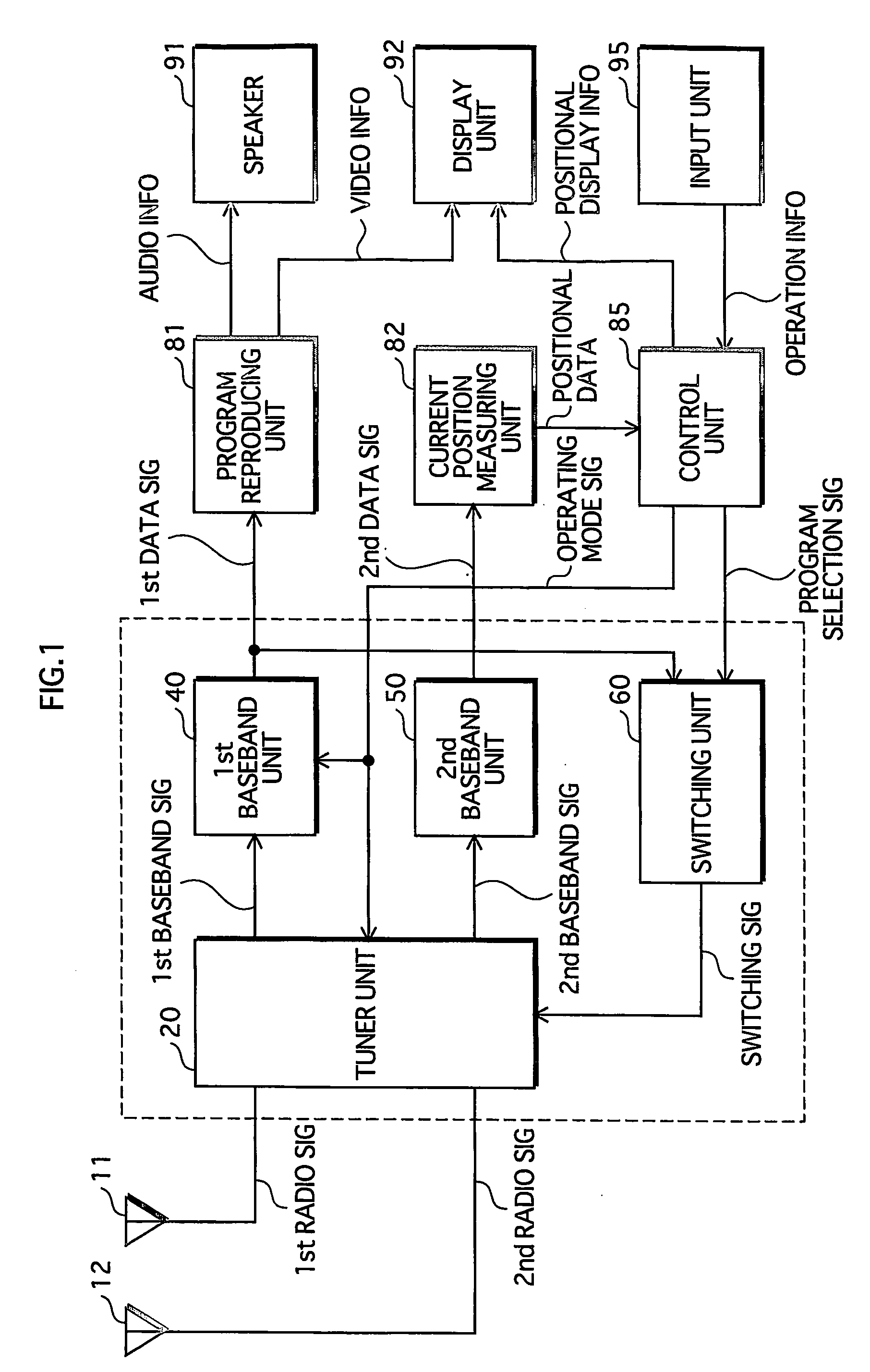
[0050]FIG. 1 is a functional block diagram showing the overall structure of the wireless terminal device of the embodiment 1.

[0051]A first antenna 11 selectively receives the ...

embodiment 2

[0084]An embodiment 2 differs from the embodiment 1 in that a wireless terminal device of the present embodiment is adapted for the second service which is a bidirectional communication service as well as for the first service mentioned above.

[0085]Examples of the second service that the wireless terminal device of the present embodiment handles include a wireless Internet access service (of which access points are known as hotspots), a wireless LAN (Local Area Network), and remote control of home appliances. Further, examples of information that is displayed relating to the second service along with the selected program include a Website, another program that is broadcast via the Internet separately from the program of the first service, the states of the home appliances controlled.

[0086]Hereinafter, description is given mainly to the differences from the embodiment 1.

(Overall Structure)

[0087]FIG. 6 is a functional block diagram showing the overall structure of a wireless terminal ...

embodiment 3

[0095]A wireless terminal device of an embodiment 3 is different from that of the embodiment 1 in the detailed structure of the tuner unit 20.

[0096]Hereinafter, description is given mainly to the difference from the embodiment 1.

(Detailed Structure of Main Part)

[0097]FIG. 7 is a functional block diagram showing the detailed structure of a main part of the wireless terminal device according to the embodiment 3. Different from the main part of the embodiment 1, the main part of the present embodiment includes a tuner unit 35 that is composed of two circuitry blocks of a first tuner 36 and a second tuner 37. Further, a power-saving control unit 65 is additionally included for controlling power supply.

[0098]The first tuner 36 and the second tuner 37 are separately provided with a local oscillator and a frequency converter. The first tuner 36 frequency converts the first radio signal to the first baseband signal, and the second tuner 37 frequency converts the second radio signal to the s...


PUM


Abstract

A first switching circuit (21) outputs a first radio signal representing a plurality of time-division multiplexed pro-grams and a second radio signal other than the first radio signal, one at a time according to a switching signal. A voltage control oscillator (27) outputs a local signal at a frequency suitable for whichever signal outputted. Using the local signal generated, a frequency converter (24) frequency converts the first and second radio signals to first and second baseband signals, respectively. Via a second switching circuit (31), a first baseband unit (40) and a second baseband unit (50) are supplied with the first and second baseband signals, respectively, and demodulate them to first and second data signals. A switching unit (60) supplies the switching signal indicating periods during which the first radio signal represents a user-selected program, to a tuner unit (20) where the first and second radio signals are processed by time-sharing.

Description

TECHNICAL FIELD[0001]The present invention relates to a wireless terminal device. More particularly, the present invention relates to a wireless terminal device for receiving a broadcast signal representing a plurality of time-division multiplexed programs to reproduce a user-selected program, and also receiving another radio signal to conduct predetermined processing.BACKGROUND ART[0002]In recent years, with the growing trend toward digital broadcasting, digital television and radio broadcasting services have been launched throughout the world.[0003]Especially in Europe, DVB-T (Digital Video Broadcasting-Terrestrial) and DAB (Digital Audio Broadcasting) services of transmitting a plurality of programs by time-division multiplexing are already available. In addition, mobile reception of the broadcast with PDAs (Personal Digital Assistances) is under development.[0004]Turning now to the field of communications, more and more AV (Audio Visual) devices are equipped with Bluetooth and w...

Claims


Application Information

Patent Timeline
Patent Type & Authority Applications(United States)
IPC IPC(8): H04B7/212H04B1/00H04B1/16H04B1/38H04H40/18H04H60/51H04N21/414H04N21/426H04Q7/38
CPCH03J2200/12H04H20/42H04N21/4263H04H60/51H04N21/41407H04H40/18
Inventor KATO, HISAYAOZEKI, HIROAKI
Owner PANASONIC CORP
Why Eureka
Try Eureka