Circuit and method for differential signaling receiver

a circuit and receiver technology, applied in the field of circuit and method for differential signaling receivers, can solve the problems of invalidating differential signals, sacrificing circuit efficiency, consumption and manufacturing costs

Inactive Publication Date: 2008-07-10
RICOH ELECTRONIC DEVICES CO LTD
View PDF5 Cites 10 Cited by
  • Summary
  • Abstract
  • Description
  • Claims
  • Application Information

AI Technical Summary

Problems solved by technology

Thus, the receiver invalidates the differential signal when the communication link is in a squelch state.
Such a circuit design may provide stability in squelch detection without increasing power consumption and manufacturing cost, but involves a complicated structure which may sacrifice efficiency in the circuit.
However, this conventional method may be impractical when used with a serial data interface such as USB 2.0 interfaces.
Both of these conventional approaches are made to enhance performance of a squelch detector, which may have limited effectiveness in providing reliable data transmission.

Method used


Image

  • Circuit and method for differential signaling receiver
  • Circuit and method for differential signaling receiver
  • Circuit and method for differential signaling receiver

Examples


Embodiment Construction

[0025]In describing preferred embodiments illustrated in the drawings, specific terminology is employed for the sake of clarity. However, the disclosure of this patent specification is not intended to be limited to the specific terminology so selected, and it is to be understood that each specific element includes all technical equivalents that operate in a similar manner.

[0026]Referring now to the drawings, wherein like reference numerals designate identical or corresponding parts throughout the several views, example embodiments of the present patent application are described.

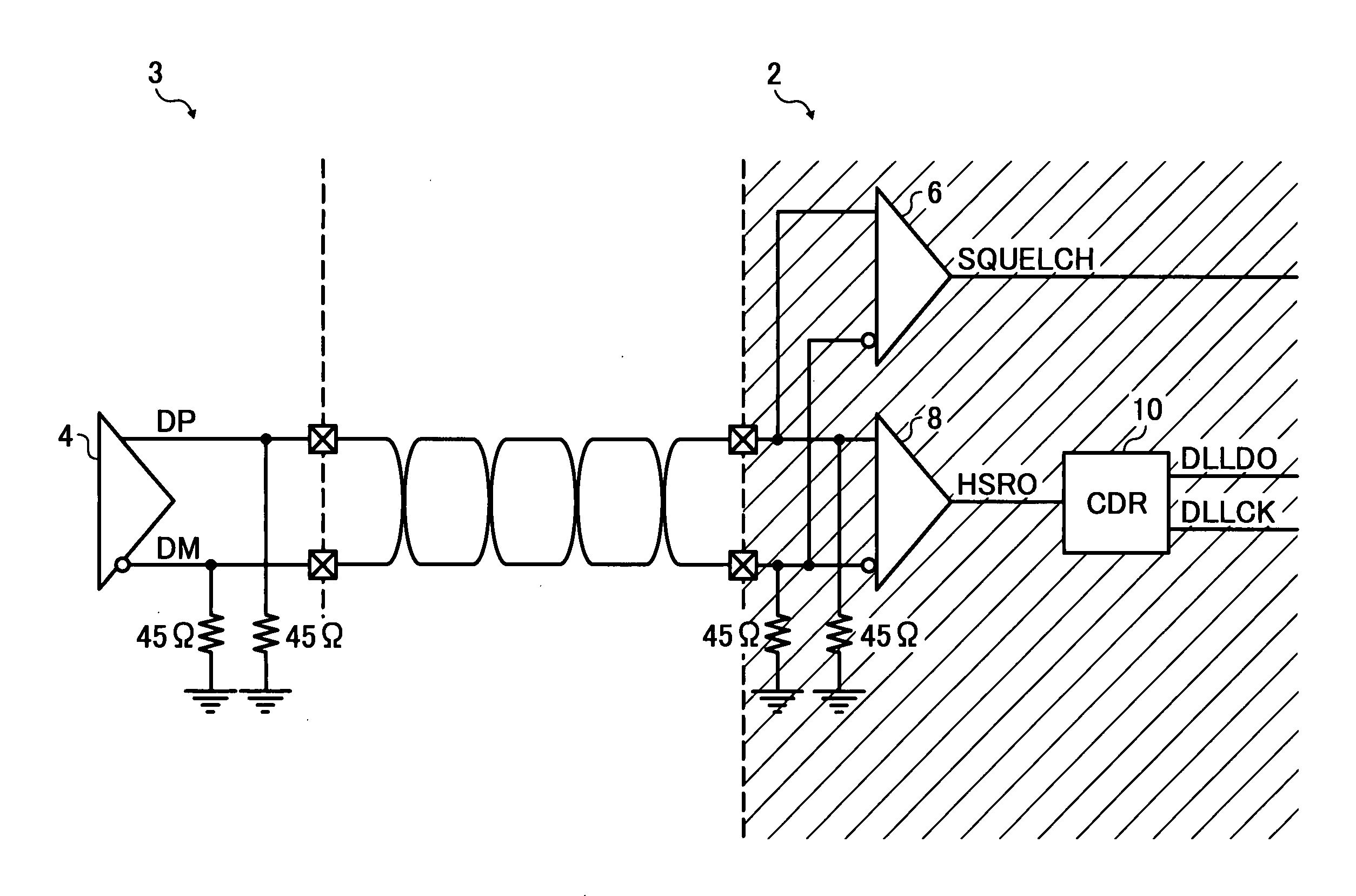
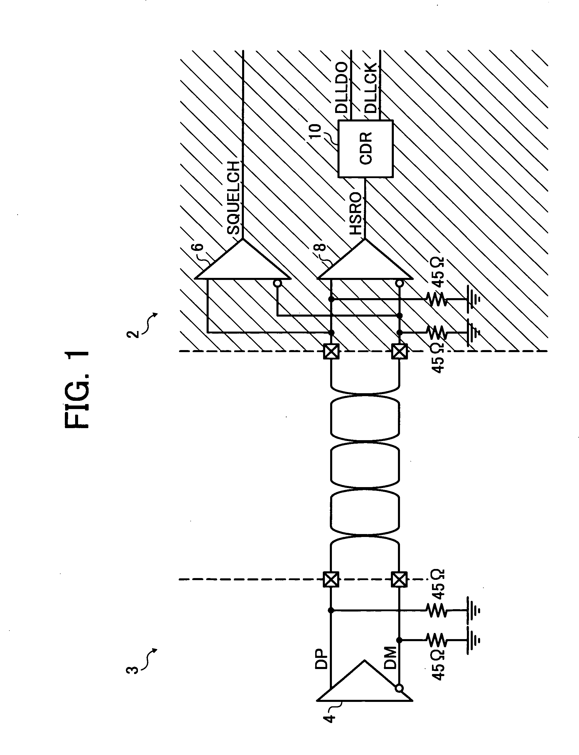
[0027]Referring to FIG. 1 of the drawings, a circuit diagram illustrating an analog front end (AFE) 2 of a differential receiver circuit 12 (see FIG. 3) according to at least one example embodiment of this patent specification is described.

[0028]In FIG. 1, the AFE 2 includes a squelch detector 6, a differential comparator 8, and a clock data recovery (CDR) circuit 10. The AFE 2 is linked to a differential tra...


PUM


Abstract

A receiver for a differential signal transmitted over a serial interface includes a squelch detector, a differential amplifier, a start pattern detector, an end pattern detector, and a controller. The squelch detector is configured to output a squelch signal when determining that the differential signal is present on the serial interface. The differential amplifier is configured to extract binary data from the differential signal. The start pattern detector is configured to indicate a first state when detecting a given start pattern in the binary data. The end pattern detector is configured to indicate a second state when detecting a given end pattern in the binary data. The controller is configured to activate the start pattern detector in response to the squelch signal. The controller is configured to validate the differential signal in the first state. The controller is configured to end receiving the differential signal in the second state.

Description

CROSS-REFERENCE TO RELATED APPLICATIONS[0001]This application claims priority from Japanese Patent Application No. 2007-002271, filed on Jan. 10, 2007 in the Japanese Patent Office, the entire contents of which are incorporated by reference herein.FIELD OF THE INVENTION [0002]The present invention relates to a circuit and method for differential signaling receiver, and more particularly, to a receiver circuit and a method used to receive a differential signal transmitted over a serial interface.DISCUSSION OF THE BACKGROUND[0003]Differential signaling is a data transfer technique widely used in digital and analog data interfaces due to its high noise immunity during data transmission. An example using a differential signaling interface is universal serial bus (USB), which is used to interconnect digital devices such as personal computers, printers, and scanners, as well as digital recording devices including digital versatile discs (DVDs) and digital video cameras. Currently, USB int...

Claims


Application Information

Patent Timeline
Patent Type & Authority Applications(United States)
IPC IPC(8): H03D1/00H04L27/06
CPCH04J3/0623H04L7/042H04L25/4906H04L25/0292H04L25/0272H04L25/02
Inventor MORIWAKI, ISAMU
Owner RICOH ELECTRONIC DEVICES CO LTD
Why Eureka
Try Eureka