
Image processing apparatus, method and program thereof

a technology of image processing and image, applied in the field of image processing apparatus, method and program thereof, can solve the problems of increasing processing load and deteriorating detection precision, and achieve the effect of improving the performance of detecting features

Inactive Publication Date: 2008-07-10
ORMON CORP
View PDF2 Cites 56 Cited by
  • Summary
  • Abstract
  • Description
  • Claims
  • Application Information

AI Technical Summary

Benefits of technology

[0008]The present invention has been made in view of such circumstances, and its object is to improve the performance of detecting the features of an object.

Problems solved by technology

However, in the case of extracting the feature point based on the feature amount, the number of feature points extracted for an object at a distant location is insufficiently small, deteriorating the detection precision.
On the other hand, the number of feature points extracted for an object at a nearby location is unnecessarily large, increasing the processing load.

Method used


Image

  • Image processing apparatus, method and program thereof
  • Image processing apparatus, method and program thereof
  • Image processing apparatus, method and program thereof

Examples


Embodiment Construction

[0054]Hereinafter, an embodiment of the present invention will be described with reference to the accompanying drawings.

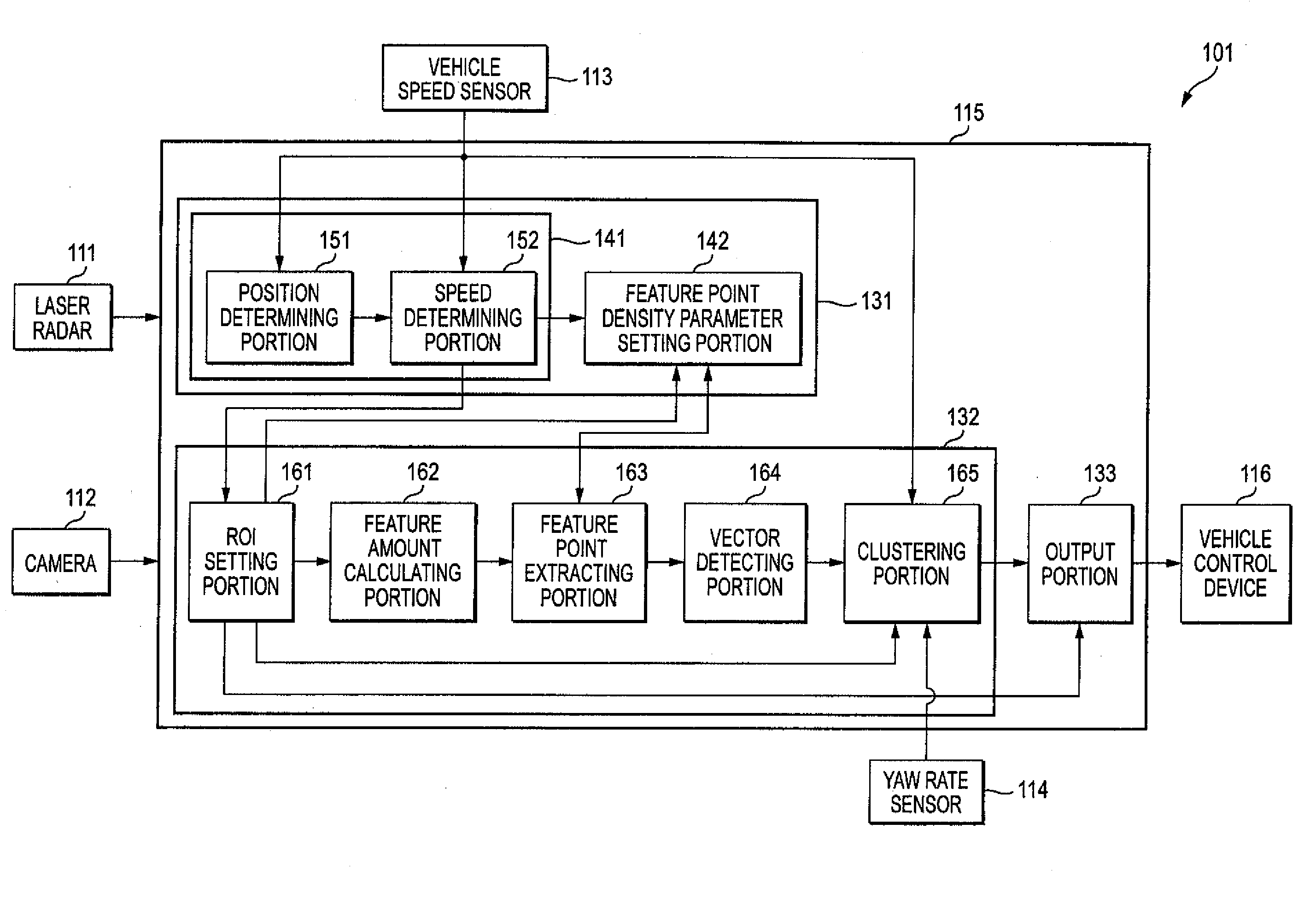
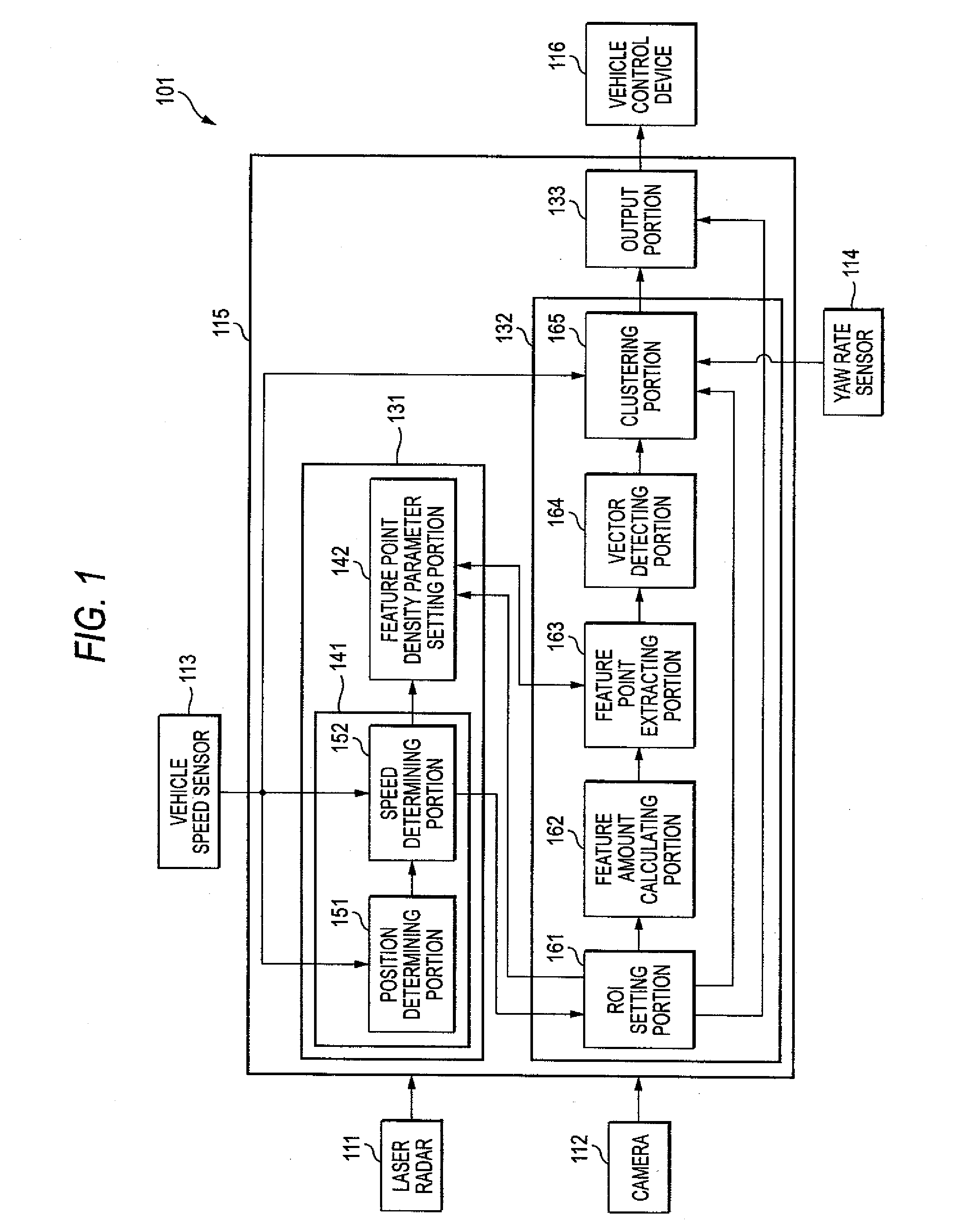
[0055]FIG. 1 is a block diagram showing one embodiment of an obstacle detection system to which the present invention is applied. The obstacle detection system 101 shown in FIG. 1 is provide on a vehicle, for example, and is configured to detect persons (for example, pedestrians, stationary persons, etc.) in the forward area of the vehicle (hereinafter also referred to as an automotive vehicle) on which the obstacle detection system 101 is provided and to controls the operation of the automotive vehicle according to the detection results.

[0056]The obstacle detection system 101 is configured to include a laser radar 111, a camera 112, a vehicle speed sensor 113, a yaw rate sensor 114, an obstacle detecting device 115, and a vehicle control device 116.

[0057]The laser radar 111 is configured by a one-dimensional scan-type laser radar, for example, that scans in a hori...


PUM


Abstract

The performance of detecting the features of an object is to be improved. In one step, among pixels within a ROI, pixels whose feature amount is greater than a predetermined threshold value are extracted as a feature point candidate. In another step, a feature point density parameter is set based on a distance to an object within the ROI. In another steps, the feature points are extracted from the feature point candidates in the descending order of the feature amount, while the feature point candidates, whose distance from the extracted feature points is equal to or smaller than the feature point density parameter, are not extracted as the feature point. In another step, a feature point list representing the feature points extracted from the ROT is output. The present invention can be applied to an in-vehicle obstacle detecting device.

Description

BACKGROUND OF THE INVENTION[0001]1. Field of the Invention[0002]The present invention relates to an image processing apparatus, method and program thereof, and more particularly, to an image processing apparatus, method and program thereof, for detecting the features of an object.[0003]2. Description of Related Art[0004]In related-art in-vehicle image processing apparatuses, there is proposed a technology in which the size and position of the image data that are subjected to an image analysis process are changed based on a fade-out coordinate, a vehicle speed, and a yaw rate of the vehicle about its vertical axis (see WO2005 / 24754 (Patent Document 1), for example).[0005]In the past, there is also proposed a technology in which the boundaries of subjects are specified based on distance information of the subjects for each of predetermined partial regions within an image, and a predetermined subject is trimmed or emphasized (see JP-A-2006-311505 (Patent Document 2), for example).[0006...

Claims


Application Information

Patent Timeline
IPC IPC(8): G06K9/00G01S17/86G01S17/89G01S17/931G06V10/771
CPCB60R1/00G01S7/4802G01S17/023G01S17/89G06K9/00805G06K9/00369G06K9/6228G06T7/0042G01S17/936G06T7/73G01S17/86G01S17/931G06V40/103G06V20/58G06V10/771G06F18/211
Inventor IKETANI, TAKASHI
Owner ORMON CORP
Learn More