Wind turbine blade brush

a technology of wind turbine blades and brushes, which is applied in the direction of liquid fuel engines, marine propulsion, vessels, etc., can solve the problems of being a major source of noise, and achieve the effects of reducing noise produced by rotor blades, improving system noise emissions, and reducing noise emissions

Inactive Publication Date: 2008-07-10
GENERAL ELECTRIC CO
View PDF8 Cites 82 Cited by
  • Summary
  • Abstract
  • Description
  • Claims
  • Application Information

AI Technical Summary

Benefits of technology

[0006]Conventional methods to reduce noise produced by the rotor blade of a wind turbine include mainly the modification of the airfoil's profile during design. In the present invention, it is proposed to dispose a number of bristles or fibres on part of a wind turbine blade in order to reduce noise emissions. The present invention bears significant advantages over the known art. First of all, the invention can be applied to an arbitrary airfoil, not depending on the aerodynamic design thereof. Hence, an airfoil for use with the present invention can be designed with the goal of best performance in terms of efficiency and the like, while still achieving improved noise emissions behaviour of the system. The measures used are made from commercially available goods, typically man made fibres, and are both easy to produce and relatively cheap. Furthermore, the invention can both be applied during the production process of a blade or to an existing wind energy system with relatively little effort and costs. The bristles can be applied to the blade by a variety of methods such as gluing, fusing, heat-sealing etc. or by mechanical insertion into small pinholes provided on the blade body or an intermediate carrier element. Rotor blades according to the present invention may be used in wind turbines with one, two, three or more rotor blades.

Problems solved by technology

As areas suitable for their economical operation are relatively scarce in a number of countries, a growing number of wind energy systems are located close to populated areas.
As the running of wind turbines in wind energy systems causes noise, this leads to various problems, such as resistance from neighbourhoods and the like.
Moreover, even a design optimized for low noise operation still causes emissions, which may be intolerable under certain conditions.
So-called slats, which are the equivalent of a landing flap, but located on the front side of the wing, are known to be a major source of noise during take-off and landing.

Method used


Image

  • Wind turbine blade brush
  • Wind turbine blade brush
  • Wind turbine blade brush

Examples


Embodiment Construction

[0026]Reference will now be made in detail to the various embodiments of the invention, one or more examples of which are illustrated in the figures. Each example is provided by way of explanation of the invention, and is not meant as a limitation of the invention. For example, features illustrated or described as part of one embodiment can be used on or in conjunction with other embodiments to yield yet a further embodiment. It is intended that the present invention includes such modifications and variations.

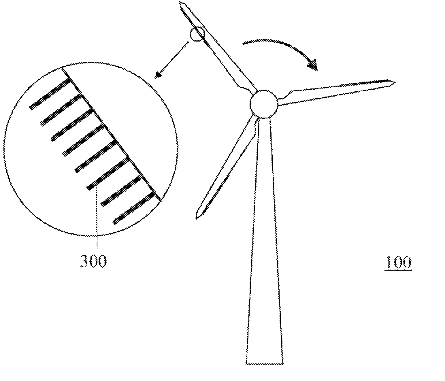
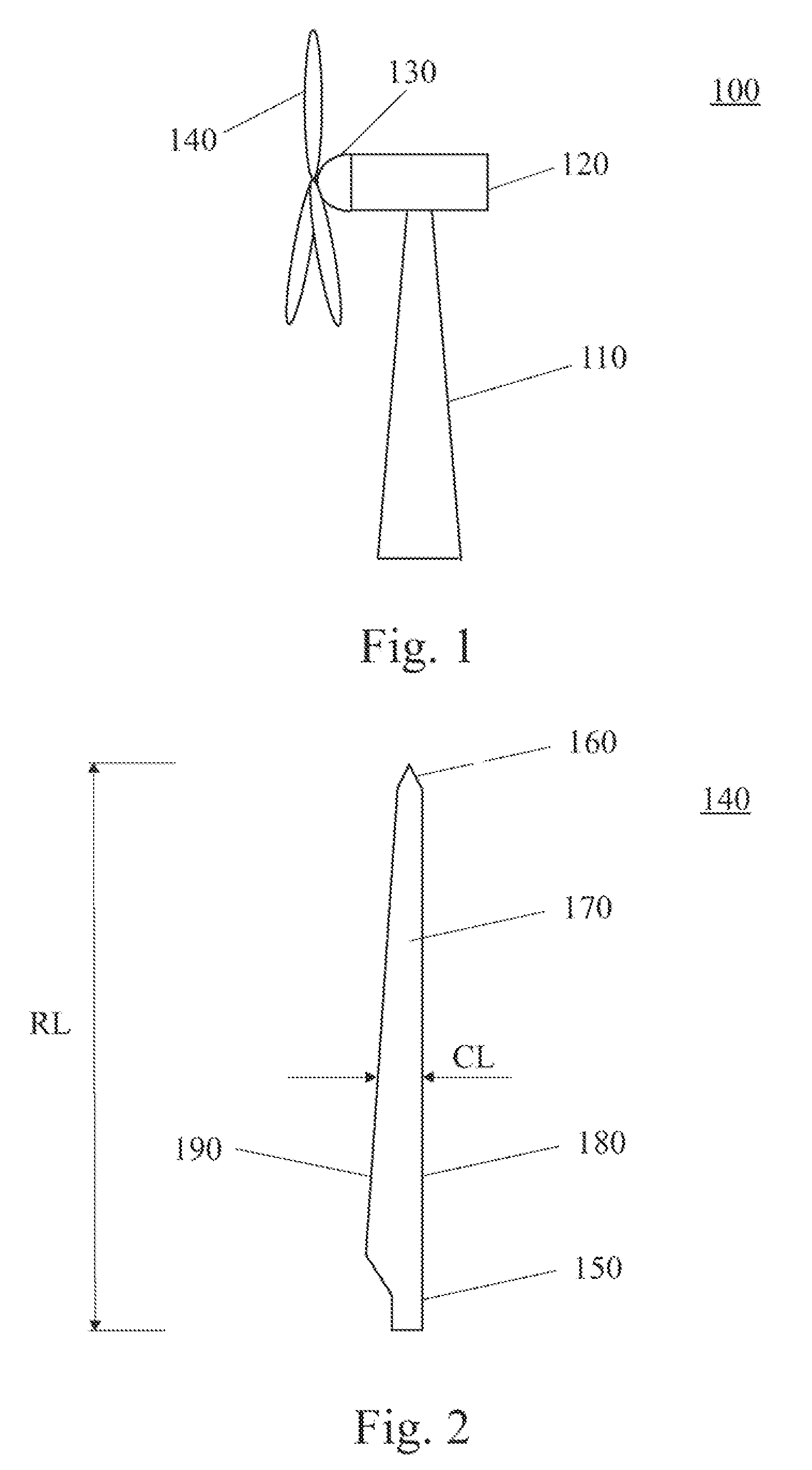
[0027]FIG. 1 is a schematic view of a typical wind turbine. The wind turbine 100 includes a tower 110 to which a machine nacelle 120 is mounted at its top end. The nacelle houses a drive train to which a main electric generator is connected (not shown). A hub 130 bearing three rotor blades 140 is mounted to a lateral end of the machine nacelle 120. The rotor blades 140 can be adjusted by pitch drives which are typically accommodated inside hub 130.

[0028]The basic configuration ...


PUM


Abstract

A wind turbine blade for use in a wind energy system comprises a blade body having a trailing edge and a leading edge, and a plurality of bristles disposed on an outer surface of said blade body. The bristles are typically attached to said blade body in the vicinity of said trailing edge and serve to reduce noise caused by the airflow around the blade during operation.

Description

BACKGROUND OF THE INVENTION[0001]The present invention relates to a wind turbine blade with bristles or a brush disposed on an outer surface thereof. The present invention further relates to a wind energy system including the same.[0002]Wind energy systems have gained more and more importance as a source of energy in recent years. As areas suitable for their economical operation are relatively scarce in a number of countries, a growing number of wind energy systems are located close to populated areas. As the running of wind turbines in wind energy systems causes noise, this leads to various problems, such as resistance from neighbourhoods and the like. Though a variety of sources contribute to the overall noise emission of such systems, air flow around the blades is known to be one of the main sources. This causes, for example, typical “hissing” or “swishing” sounds in the 1 kHz frequency range. Sound levels are greatly influenced by the design of the turbine blades, especially the...

Claims


Application Information

Patent Timeline
Patent Type & Authority Applications(United States)
IPC IPC(8): F01D5/14F04D29/38
CPCF03D1/065F04D29/38Y02E10/721F05D2240/122F05D2240/304F05B2260/96Y02E10/72
Inventor HERR, STEFANKOEGLER, KLAUSDOBRZYNSKI, WERNER
Owner GENERAL ELECTRIC CO
Why Eureka
Try Eureka