Fluid Barrel-Polishing Device and Polishing Method

Active Publication Date: 2008-07-10
SINTOKOGIO LTD
View PDF10 Cites 0 Cited by
  • Summary
  • Abstract
  • Description
  • Claims
  • Application Information

AI Technical Summary

Benefits of technology

[0012](1) the inner cylinder 4 prevents the formation of the open space of the mass that would have been formed in a polishing device that is made by a conventional technology, and
[0014]Accordingly, the pressure of the mass (M) also works on the inner surface of it, and it achieves an effect that increases the contact pressure between the workpieces and media that compose the mass (M) and increases the polishing ability of the device.
[0018](1) the inner cylinder puts pressure on the mass in a direction going from the inside of it to the lateral wall of the fixed tank. Accordingly, it works based on the contact pressures between the workpiece and the medium (and the abrasive compound and the water if the device is a wet type), and increases the polishing ability, and
[0019](2) the inner cylinder decreases the radial area in which the mass is fluidized in the fixed tank. Accordingly, the height of the upper surface of the mass is increased, and the upper part of the mass puts pressure on the internal part of it and this pressure also increases the polishing ability.
[0021]When a conventional fluid barrel-polishing device is used, the more the polishing ability is increased, the more the wear of the media is increased, and the efficiency for the polishing (i.e., the amount polished of the workpieces divided by the amount the media is worn) is decreased. The polishing of the workpieces wears the media. However, the rubbing between media, i.e., the contact pressure between them and the differences of the relative velocities between them, wears the media far more than the wear caused by the polishing of the workpieces.
[0024]As shown in the examples below, the polishing of the workpieces was increased by 1.4-2.4 times more than that of the conventional technology that had no inner cylinder. In contrast, the wear of the media was increased by just 1.2-1.4 times more than that of the conventional technology. Accordingly, the efficiency for the polishing was increased by 1.2-1.7 times. Namely, the wear of the media can be decreased in order to polish a certain number of workpieces and the polishing ability can be increased compared to the wear of the media. Therefore, the running cost of the media can be decreased, the time necessary to polish can be decreased, and the productivity can be increased.

Problems solved by technology

However, the mass (M), which is composed of the workpieces and the media, is only moved downward to the center of rotation from the lateral wall of the fixed tank 11 after it is driven to the summit by the climbing force (B), but this creates the following problems.(1) An “open space” that is an air hole located above the center of rotation is formed.(2) In the part of the mass (M) that neighbors the open space, the contact pressure (i.e., the polishing ability, and the efficiency for the polishing) is reduced.

Method used


Image

  • Fluid Barrel-Polishing Device and Polishing Method
  • Fluid Barrel-Polishing Device and Polishing Method
  • Fluid Barrel-Polishing Device and Polishing Method

Examples


examples 1 and 2

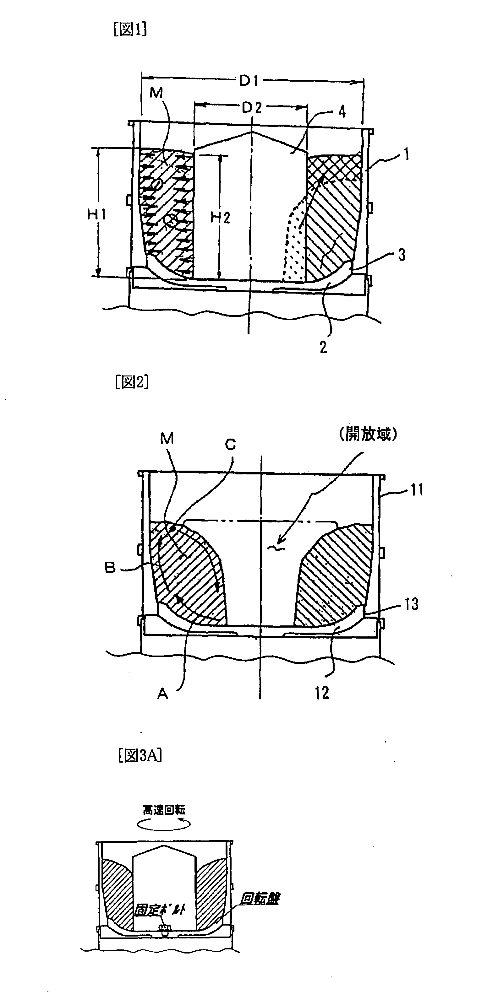
[0044]The fluid barrel-polishing devices that are shown in Table 1 were tested. Examples 1 and 2 had an inner cylinder 4 that was put on the center of rotation of a turntable 2, but comparative example 1 had no inner cylinder. The common testing conditions were that hard test pieces made of a material S45C and soft test pieces made of a material A2017 were used as the objects to be polished (hereafter, “workpieces”), a material that had a cone shape with a 20 mm bottom diameter, an abrasive compound, and water, were used as an abrasive material (hereafter, “media”), the velocity of the rotation of the turntable 2 was 250 min−1, and the time for polishing was 30 min.

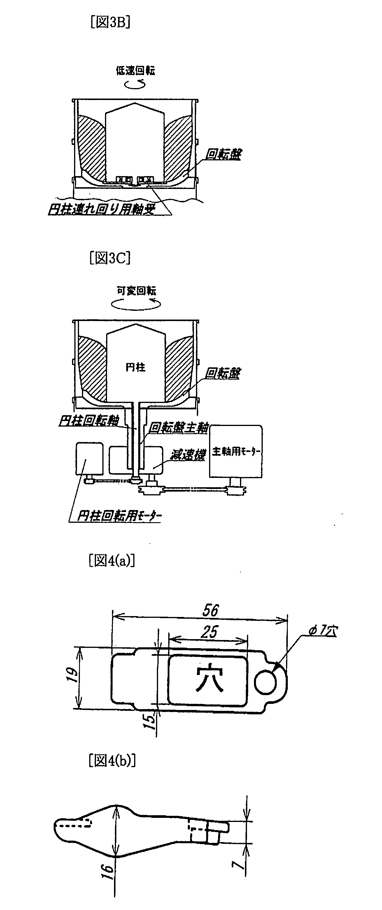
[0045]The inner cylinder 4 of examples 1 and 2 had a diameter of 220 mm. In example 1, it was tightly fixed on the center of rotation of the turntable 2, as shown in FIG. 1, and the velocity of its rotation was the same as that of the turntable 2 (250 min−1). In example 2, the inner cylinder 4 was not tightly fixed on the...

examples 3 , 4

EXAMPLES 3, 4, and 5

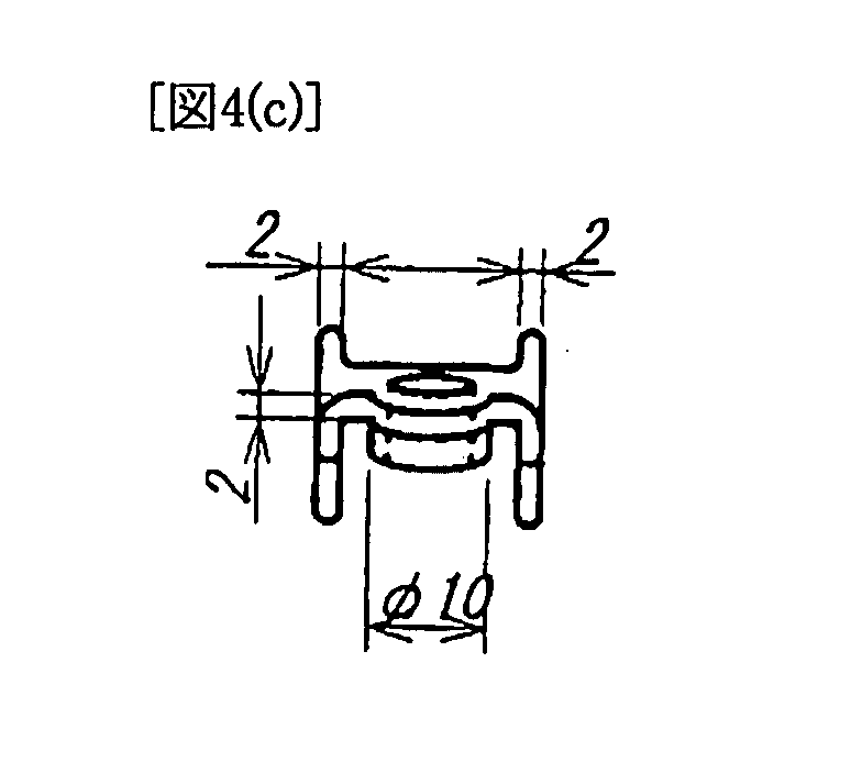
[0058]The fluid barrel-polishing devices that were listed in Table 3 were tested. Examples 3, 4, and 5 had an inner cylinder 4, which was put on the center of rotation of a turntable 2. But comparative example 2 had no inner cylinder. The common testing condition was that actual workpieces, which were rocker arms used as automotive parts and were made of SCM, were used as the objects to be polished (workpieces). Test pieces that were made of the same material as the actual workpieces were used for reference. Fired ceramic that was harder, smaller, and had a larger specific gravity than the one used in examples 1 and 2, an abrasive compound, and water were used as media. The velocity of the rotation of the turntable 2 was 250 min−1, and the time for polishing was 30 min. The shape of the workpiece, which is the rocker arm used as an automotive part, is shown in FIG. 4.

[0059]As for the inner cylinder 4, in examples 3 and 4 the outside diameter of it was 220 mm, whi...


PUM

PropertyMeasurementUnit
Volumeaaaaaaaaaa
Volumeaaaaaaaaaa
Timeaaaaaaaaaa

Abstract

A fluid barrel-polishing device comprises a cylindrical fixed tank (1) and a turntable (2) that is located at the bottom of the tank (1) with a gap (3) that allows it to rotate horizontally, and wherein when workpieces and media are thrown in the fixed tank (1) and the turntable (2) is rotated horizontally, the workpieces and the media circulate and form themselves into a mass (M) and thereby the workpieces are polished, wherein an inner cylinder (4) is rotatably or fixedly placed coaxially on the center of the rotation of the turntable (2) and it allows the workpieces in the mass (M) to be polished with the inside of the mass (M) contacting the wall of the inner cylinder (4) and with its outside contacting the wall of the fixed tank (1).

Description

FIELD OF THE INVENTION[0001]The present invention relates to a fluid barrel-polishing device and polishing method that can increase the ability and efficiency for the polishing, increase the productivity by shortening the polishing time, and decrease the running cost by suppressing the wear of media.DESCRIPTION OF THE PRIOR ART[0002]FIG. 2 is a sectional view of a conventional fluid barrel-polishing device. As shown in FIG. 2, the conventional fluid barrel-polishing device comprises a cylindrical fixed tank 11, a turntable 12 that is located at the bottom of the tank 11, and a gap 13 that allows the turntable to rotate slidably on it.[0003]The horizontal rotation of the turntable 12 imparts a centrifugal force (A) in a direction going from the center of the rotation to the lateral wall of the fixed tank 11 to the workpieces and the media that have been put into the tank 11. The centrifugal force (A) that is imparted to the workpieces and the media is transformed into a climbing forc...

Claims


Application Information

Patent Timeline
IPC IPC(8): B24B31/108B24B31/10B24B1/00
CPCB24B31/108
Inventor WATANABE, MASATOMOSUESUGA, HIROAKI
Owner SINTOKOGIO LTD
Why Eureka
Try Eureka