Transmission mechanism and the deposition apparatus using the same

Inactive Publication Date: 2012-09-27
IND TECH RES INST
View PDF4 Cites 5 Cited by
  • Summary
  • Abstract
  • Description
  • Claims
  • Application Information

AI Technical Summary

Benefits of technology

[0006]The present disclosure relates to a transmission mechanism and a deposition apparatus using the same, by which the transmitting components, including driving wheels and shafts, can be prevented from being contaminated by reactive species that are generated from the ionization of a process gas in a film deposition process. In addition, since the transmitting components of the transmission mechanism are sealed from contacting with the reactive species, the transporting of substrates in any in-line type film deposition apparatus, including CVD apparatuses, PECVD apparatuses and PVD apparatuses, can be ensu

Problems solved by technology

Therefore, if the components used for transmitting the substrates 18, which includes the rotary magnetic fluid feedthrough, are not properly shielded or protected, there will be deposit formed on any surface that is in contact with the reactive species, and with the progress of the film deposition process, those transmitting components will begin to act abnormally.
For instance, the rotary magnetic fluid feedthrough can not rotate smoothly.
Consequently, not only the frequency of equipment maintenance is increased, but also the cost relating to component replacement is increased.
Moreover, the spreading reactive species 191 will also cause a fragile film to be formed on the surface of the O-ring 131 for each driving wheel 13, which is most like to break into small piec

Method used


Image

  • Transmission mechanism and the deposition apparatus using the same
  • Transmission mechanism and the deposition apparatus using the same
  • Transmission mechanism and the deposition apparatus using the same

Examples


Example

[0020]For your esteemed members of reviewing committee to further understand and recognize the fulfilled functions and structural characteristics of the disclosure, several exemplary embodiments cooperating with detailed description are presented as the follows.

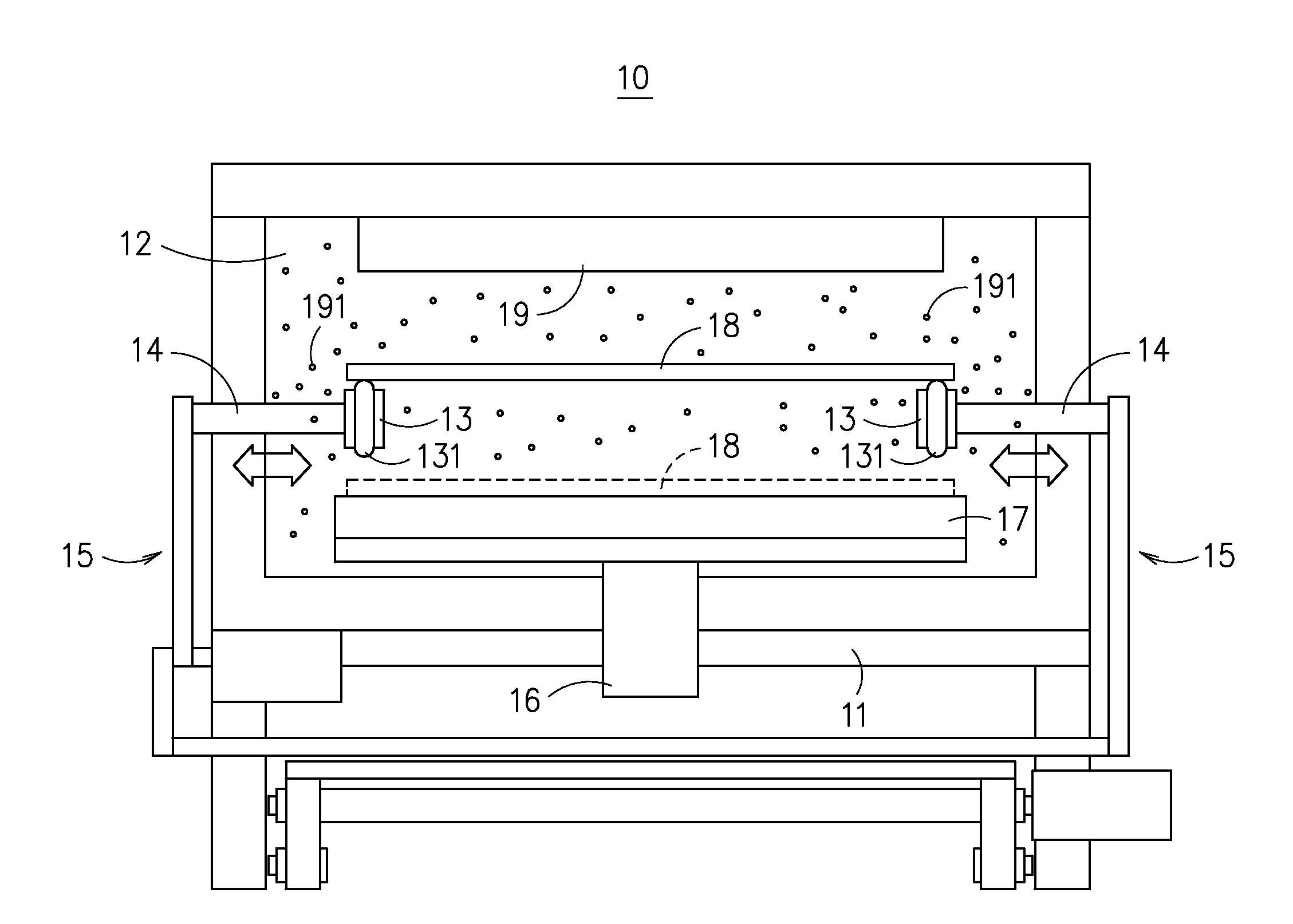
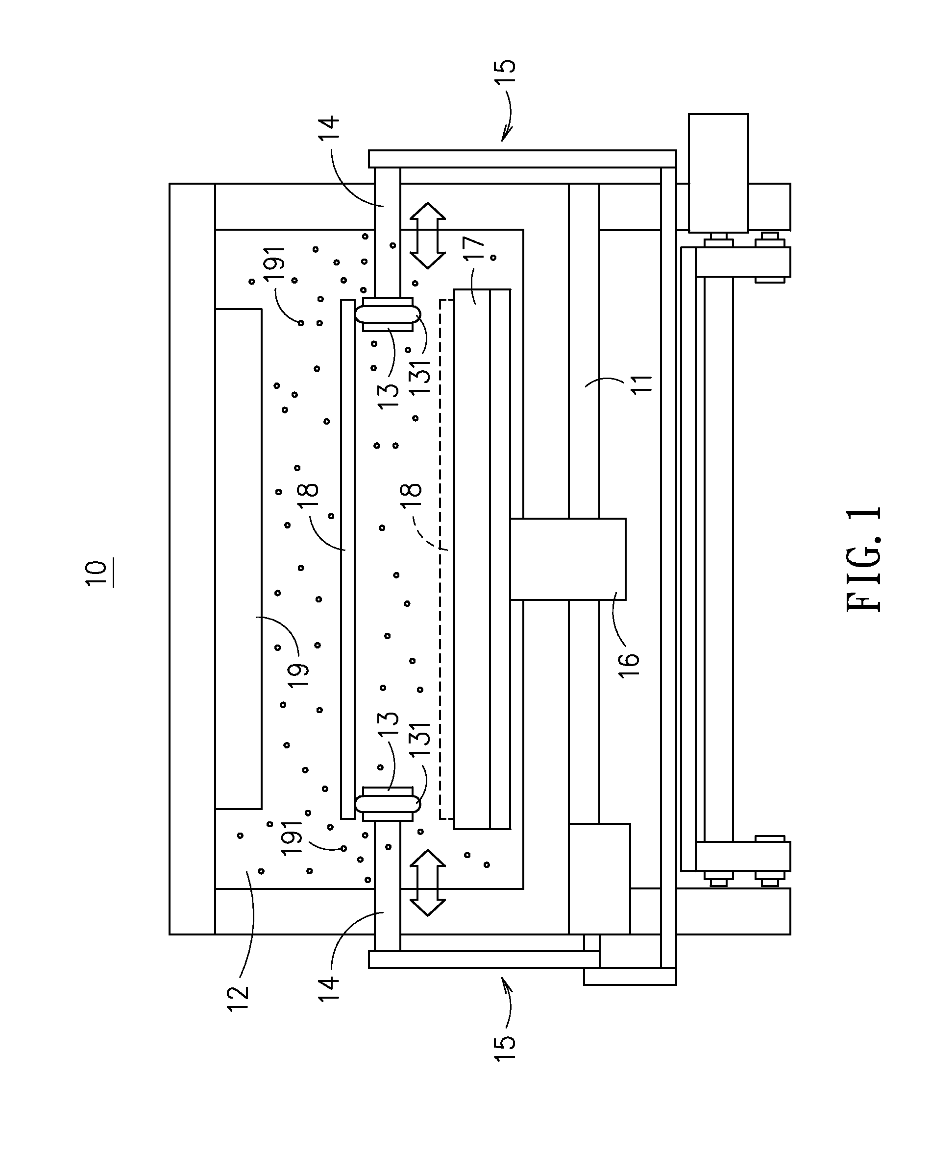
[0021]Please refer to FIG. 4, which is a schematic diagram showing a deposition apparatus according to an embodiment of the present disclosure. In FIG. 4, a deposition apparatus 100 is configured with a cavity 20, which has a shower head 30 disposed therein for spraying a process gas into the cavity 20 where it is further being ionized into reactive species 31. Moreover, the cavity 20 is mounted on a frame 40, whereas the frame 40 is configured with a lifting mechanism 50 that is provided for a hot plate 51 to be arranged on top thereof while enabling the same to be arranged inside the cavity 20. In addition, there is a plurality of transmission mechanisms 60 being arranged symmetrically inside the cavity 20 at two opposite s...


PUM

PropertyMeasurementUnit
Lengthaaaaaaaaaa
Diameteraaaaaaaaaa
Transmissionaaaaaaaaaa

Abstract

The deposition apparatus has a plurality of said transmission mechanisms arranged therein in a symmetrical manner. Each transmission mechanism comprises: a drive shaft, formed with a tapered end; a driving wheel, configured with a shaft hole for the tapered end to bore coaxially therethrough; a plurality of slide pieces, radially mounted to the driving wheel; a first elastic member, mounted enabling the plural slide pieces to be ensheathed thereby; a second elastic member, disposed between the first elastic member and the first axial end of the drive shaft while being mounted to the periphery of the driving wheel; an enclosure, configured with an opening; wherein, the driving wheel that is moving in a reciprocating manner drives the sliding pieces to slide in radial directions, thereby, causing the outer diameter of the first elastic member to change accordingly and enabling the opening of the enclosure to open or close in consequence.

Description

CROSS-REFERENCE TO RELATED APPLICATION[0001]This non-provisional application claims priority under 35 U.S.C. §119(a) on Patent Application No. 100109636 filed in Taiwan (R.O.C.) on Mar. 22, 2011, the entire contents of which are hereby incorporated by reference.TECHNICAL FIELD[0002]The present disclosure relates to a transmission mechanism and the deposition apparatus using the same, and more particularly, to a transmission mechanism, capable of preventing its transmitting components from being polluted by reactive species that are ionized by process gases, so as to be used in an in-line type deposition apparatus for enhancing the reliability and improving the quality of the films that are deposited using the deposition apparatus.TECHNICAL BACKGROUND[0003]For achieving cost and throughput advantages in optoelectronic industry, the substrates used in common in-line type film deposition apparatuses for solar cell production line are generally being transmitted inside and passing throu...

Claims


Application Information

Patent Timeline
IPC IPC(8): C23C16/50F16H57/00
CPCC23C14/564C23C14/568Y10T74/19642C23C16/54C23C16/4401
Inventor DU, CHEN-CHUNGCHIANG, MING-TUNGLIANG, MUH-WANGCHEN, KUAN-CHOUSHEN, TEAN-MUHO, JUNG-CHEN
Owner IND TECH RES INST
Why Eureka
Try Eureka