Engine control apparatus

a technology of control apparatus and engine, which is applied in the direction of electric control, machines/engines, instruments, etc., can solve the problem of inability to obtain desired heat generation quantity, and achieve the effect of good emissions and fuel economy

Active Publication Date: 2008-07-10
DENSO CORP
View PDF2 Cites 52 Cited by
  • Summary
  • Abstract
  • Description
  • Claims
  • Application Information

AI Technical Summary

Benefits of technology

[0008]With the foregoing difficulties in view, an object of the present invention is to provide an engine control apparatus, which is capable of determining a parameter useful for realizing a des

Problems solved by technology

Such device configuration may certainly prevent injection with excess injection quantity, however, another problem

Method used


Image

  • Engine control apparatus
  • Engine control apparatus
  • Engine control apparatus

Examples


Embodiment Construction

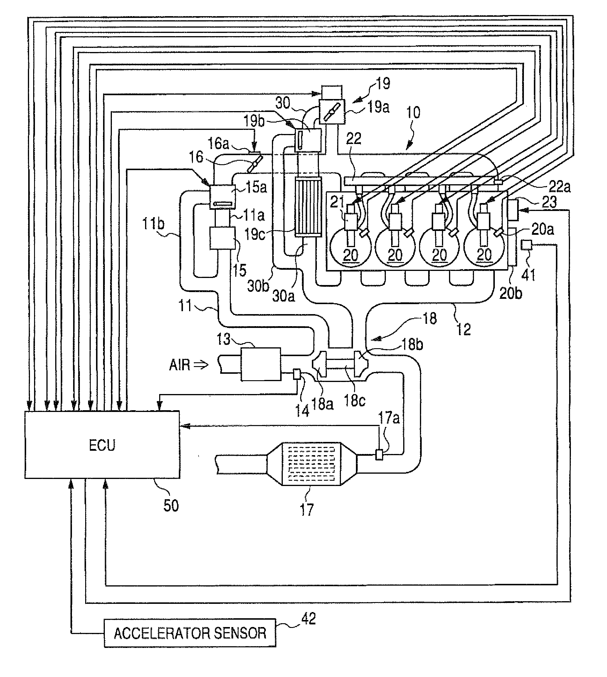
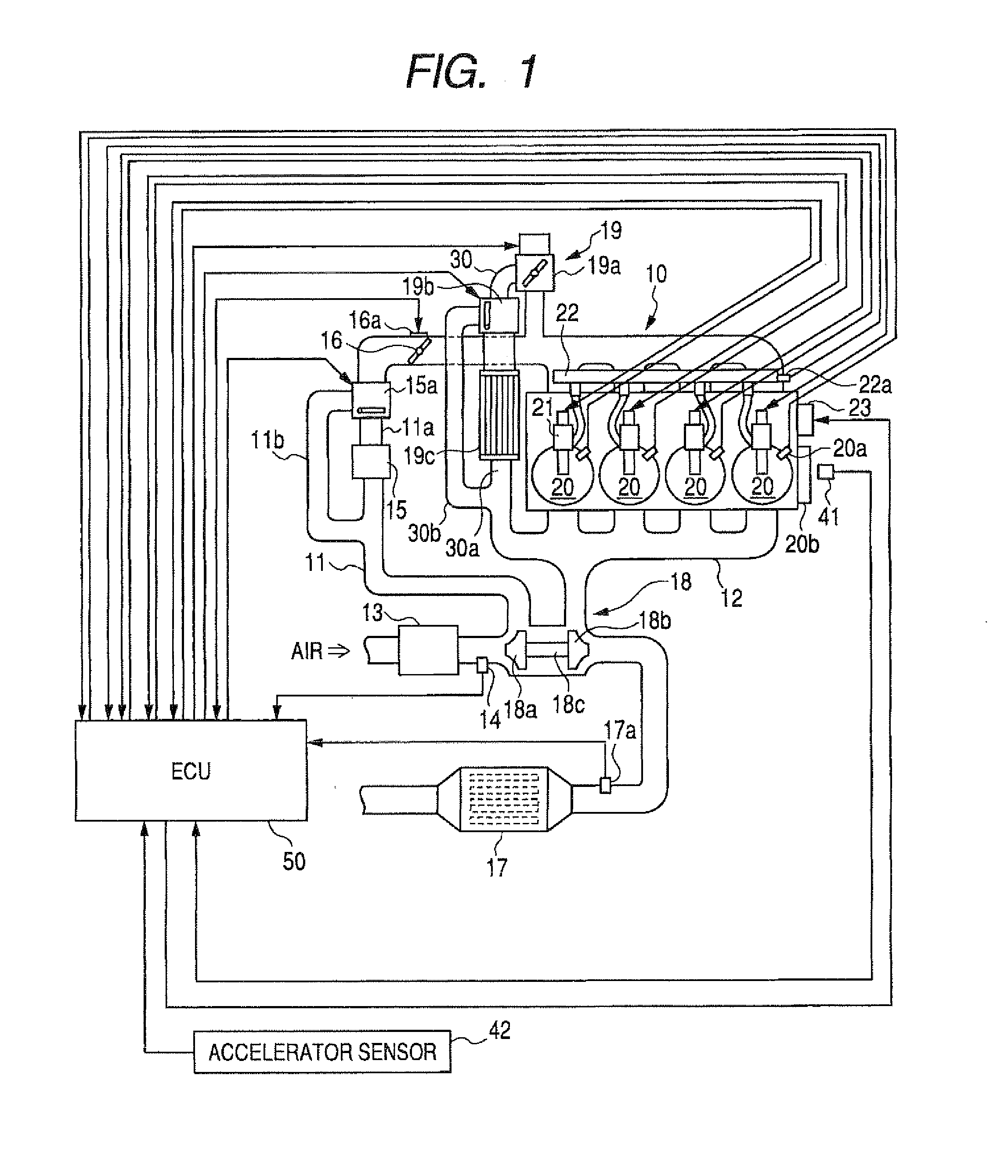
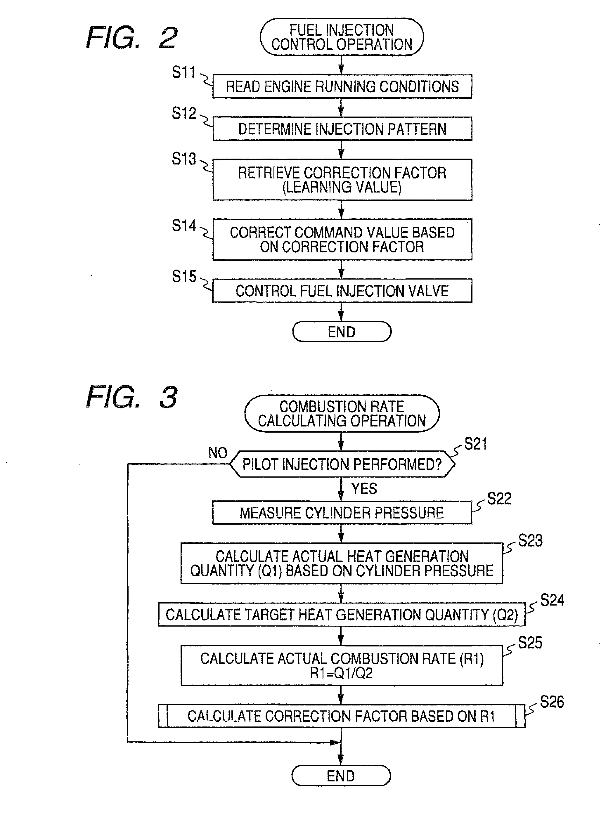
[0045]One preferred embodiment of an engine control apparatus according to the present invention will be described below in greater detail with reference to FIGS. 1 to 5. In this embodiment, the engine control apparatus is employed in an engine control system of a four-wheeled vehicle having a reciprocating engine (internal combustion engine) as a controlled object or target of the engine control system.

[0046]FIG. 1 shows a general configuration of the vehicle engine control system in which the engine control apparatus of the present invention is incorporated. As shown in FIG. 1, the engine control system is configured to control a four-cylinder reciprocating diesel engine 10 equipped with a common rail fuel injection device and includes various sensors and an electronic control unit (ECU) 50. The engine 10 forms a controlled object of the engine control system. The engine 10 as a controlled object and various essential parts or components of the engine control system will be detail...


PUM


Abstract

An engine control apparatus comprised of an engine control ECU has a program preloaded therein for determining a combustion rate (actual combustion rate) corresponding to the ratio of an ideal heat generation quantity (target heat generation quantity) estimated to be generated from a fuel supply quantity, and an actual heat generation quantity actually generated by the fuel supply quantity. The engine control apparatus controls pilot injection timing with a controlled variable corresponding to the thus determined combustion rate so as to increase the combustion rate.

Description

CROSS REFERENCE TO RELATED APPLICATION[0001]The present application is based on and claims priority from Japanese Patent Application No. 2007-1975, filed Jan. 10, 2007, the content of which is incorporated herein by reference.BACKGROUND OF THE INVENTION[0002]1. Field of the Invention[0003]The present invention relates to an engine control apparatus for controlling a target engine of the type having an output shaft rotatably driven to generate a torque on the output shaft through combustion of fuel inside a cylinder of the engine.[0004]2. Description of the Related Art[0005]As is well known, in an engine (internal combustion engine) used as a power source for a motor vehicle, for example, fuel supplied by injection from an appropriate fuel injection valve (such as an injector) is ignited and combusted to generate an output torque. In recent years, automotive diesel engines have employed a so-called “multistage injection system” in which a main injection for generating the output torq...

Claims


Application Information

Patent Timeline
IPC IPC(8): F02D45/00F02D41/02F02D41/38F02D41/40F02M35/10
CPCF02D35/02F02D35/023Y02T10/44F02D41/403F02D41/2451Y02T10/40
Inventor SASAKI, SATORUKURONITA, TOKUJI
Owner DENSO CORP
Why Eureka
Try Eureka