Exhaust device in combustion engine, and motorcycle therewith

a technology of exhaust device and combustion engine, which is applied in the direction of valve operating device, machine/engine, mechanical apparatus, etc., can solve the problems of affecting the efficiency of exhaust, so as to achieve the effect of preventing noise and satisfying exhaust efficiency

Inactive Publication Date: 2008-07-17
KAWASAKI HEAVY IND LTD
View PDF8 Cites 12 Cited by
  • Summary
  • Abstract
  • Description
  • Claims
  • Application Information

AI Technical Summary

Benefits of technology

[0024]The present invention provides a motorcycle having satisfactory exhaust efficiency and capable of e

Problems solved by technology

However, when dynamic pressure of the exhaust gas is applied on the valve body 102 in the exhaust gas flow direction and the vibration of the combustion engine is transmitted to the valve body 102 during the operation, the valve shaft 103

Method used


Image

  • Exhaust device in combustion engine, and motorcycle therewith
  • Exhaust device in combustion engine, and motorcycle therewith
  • Exhaust device in combustion engine, and motorcycle therewith

Examples


first embodiment

[0037]FIGS. 1 to 7 show an exhaust device according to a first embodiment of the present invention and an exhaust apparatus of a combustion engine for a motorcycle equipped with the same, and the first embodiment of the present invention will be described based on such drawings.

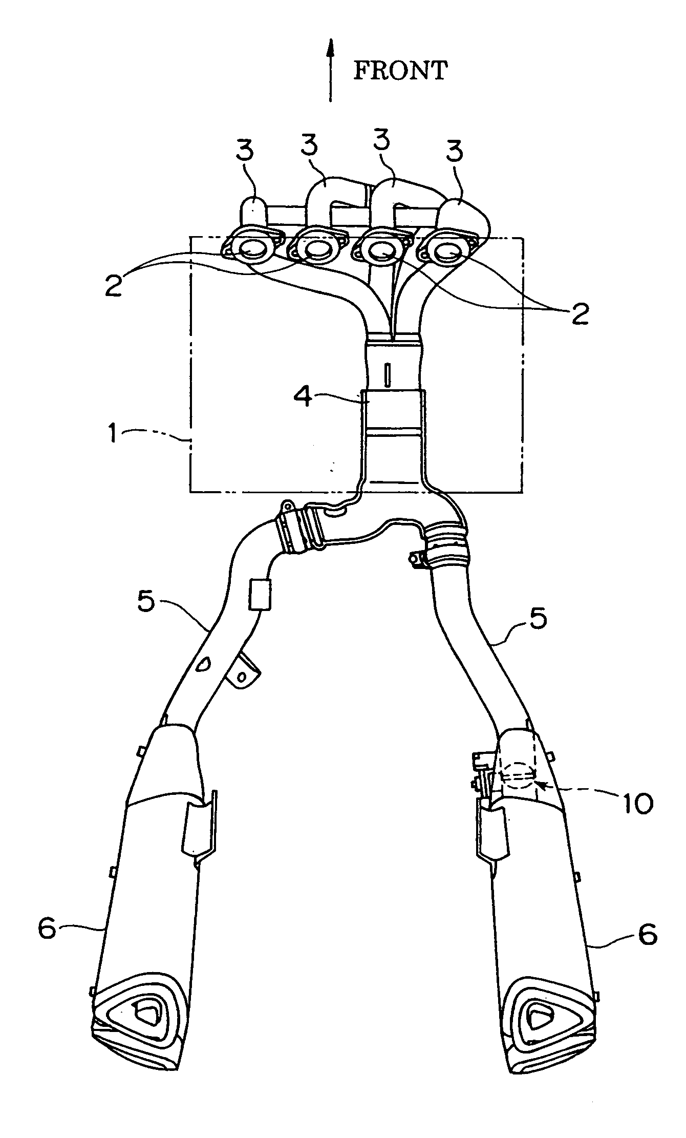
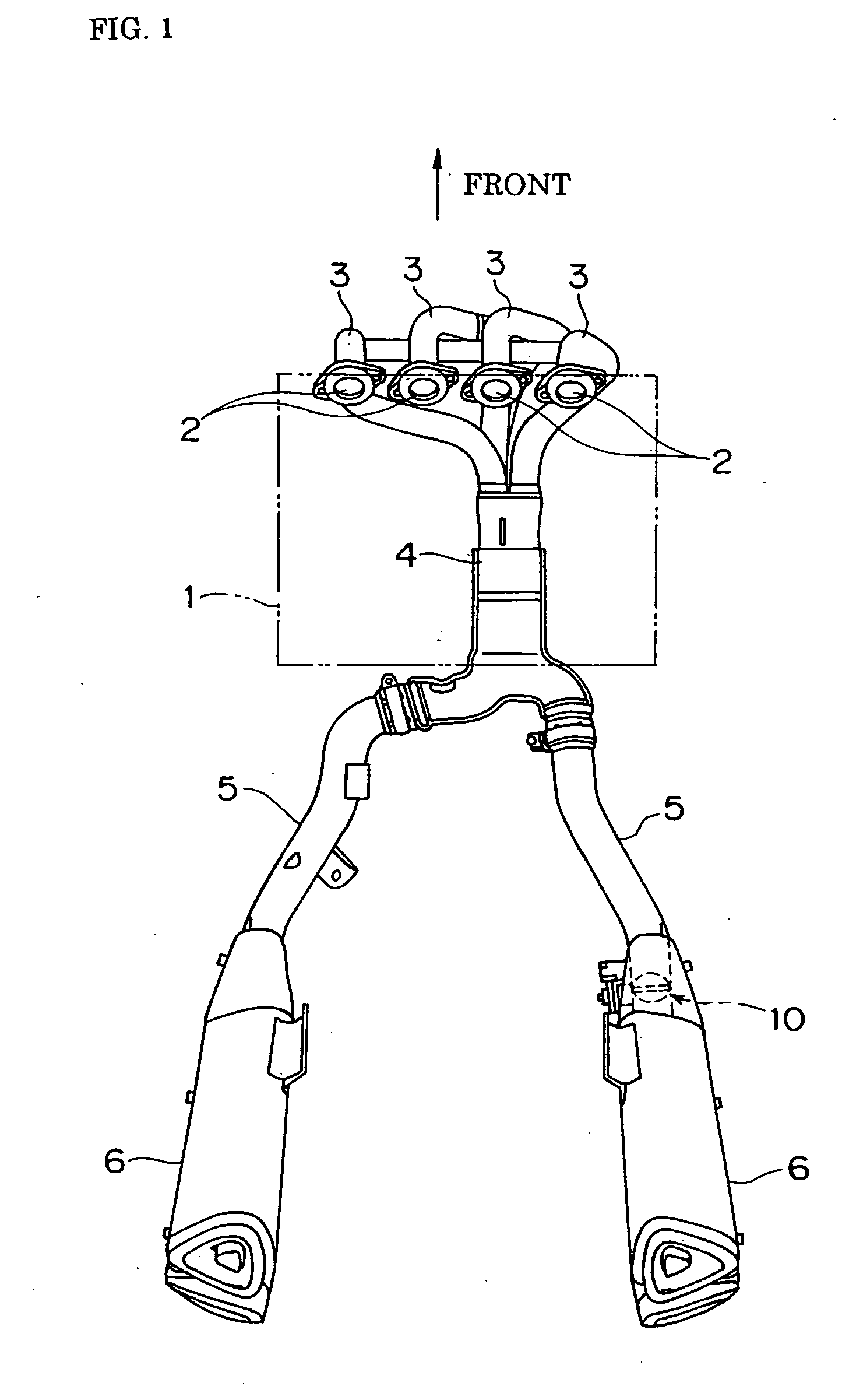
[0038]FIG. 1 is a plan view of the exhaust apparatus in the combustion engine, and FIG. 2 is a right side view of the exhaust apparatus of FIG. 1. “Forward” indicated by an arrow is the advancing direction of a vehicle. In FIG. 1, the combustion engine 1 is an inline-type 4-cylinder engine, where individual exhaust pipes 3, 3, 3, 3 are connected to corresponding exhaust ports 2, 2, 2, 2 formed at a front surface of four cylinders of the engine 1, and the four individual exhaust pipes 3, 3, 3, 3 are extended downward along the front side of the combustion engine 1, curved backward near the lower front end of the engine 1, and collected by a collection pipe 4. The collection pipe 4 is arranged under the engine ...

second embodiment

[0067]FIG. 8 shows a second embodiment and is an enlarged cross sectional view showing the same portion as FIG. 6. In the second embodiment, the left stopper 60 is configured only by the left flange 62 integrally molded to the valve shaft 16. Other configurations are the same as in the first embodiment, and the same reference numerals are denoted for the same components.

third embodiment

[0068]FIG. 9 shows a third embodiment and is an enlarged cross sectional view showing the same portion as FIG. 7. In the third embodiment, the right stopper 61 is configured by an outward right flange 65 integrally molded to the valve shaft 16, and a ring shaped metal spacer 80 sandwiched between the right flange 65 and the right bearing member 17-2. The left stopper 60 may be either a configuration combining the ring 63 and the left flange 62 as in FIG. 6 or a configuration including only the left flange 62 as in FIG. 8. Other configurations are the same as in the first embodiment, and the same reference numerals are denoted for the same components.


PUM


Abstract

The present invention relates to an exhaust device for adjusting an exhaust gas cross sectional area of an exhaust passage in a combustion engine. The exhaust device includes a valve body arranged in the exhaust passage communicating to an exhaust port of the combustion engine; a valve shaft fixed or integrally formed to the valve body and arranged so as to transverse the exhaust passage, the valve shaft changing the opening of the valve body by turning with the valve body about an axis of the valve shaft; a pair of bearing members for supporting rotatably the valve shaft at both ends thereof in a axial direction of the valve shaft; and a stopper arranged on the valve shaft so as to face an end face on the inward side of the exhaust passage of each bearing member in the axial direction. The stopper is restricted in the axial direction by the end face of each of the bearing members so that the valve body and the valve shaft do not move in the axial direction.

Description

BACKGROUND OF THE INVENTION[0001]1. Field of the Invention[0002]The present invention relates to an exhaust device in a combustion engine for controlling an exhaust gas flow in an exhaust passage to enhance exhaust efficiency etc., and a motorcycle equipped with the exhaust device.[0003]2. Description of the Prior Art[0004]Generally, as shown in FIG. 11, a exhaust device in the combustion engine has a plate-shaped valve body (butterfly valve) 102 arranged in an exhaust passage 101 in an exhaust pipe unit 100. The valve body 102 is fixed to a valve shaft 103. Both ends of the valve shaft 103 are rotatably supported by left and right bearing members 105, 05. Exhaust gas flow is controlled by changing a rotation or turn angle (opening angle) of the valve body 102 according to an operation state of the combustion engine thereby enhancing the exhaust efficiency. When the engine is in high-speed rotation, output efficiency of the engine is enhanced by positioning the valve body 102 in a f...

Claims


Application Information

Patent Timeline
IPC IPC(8): F01N7/00F01N1/08F01N13/08
CPCF01N13/04F02D9/106F02D9/04F01N13/087
Inventor KANZAWA, TATSUHIKOWAKAHARA, KAZUMASATAMAI, NAOKIKATSUKAWA, YOTASOEDA, AKIRAYAMAMOTO, HIDEHIKO
Owner KAWASAKI HEAVY IND LTD
Why Eureka
Try Eureka