
Battery voltage measuring system

Inactive Publication Date: 2008-07-17
RENESAS ELECTRONICS CORP
View PDF9 Cites 12 Cited by
  • Summary
  • Abstract
  • Description
  • Claims
  • Application Information

AI Technical Summary

Benefits of technology

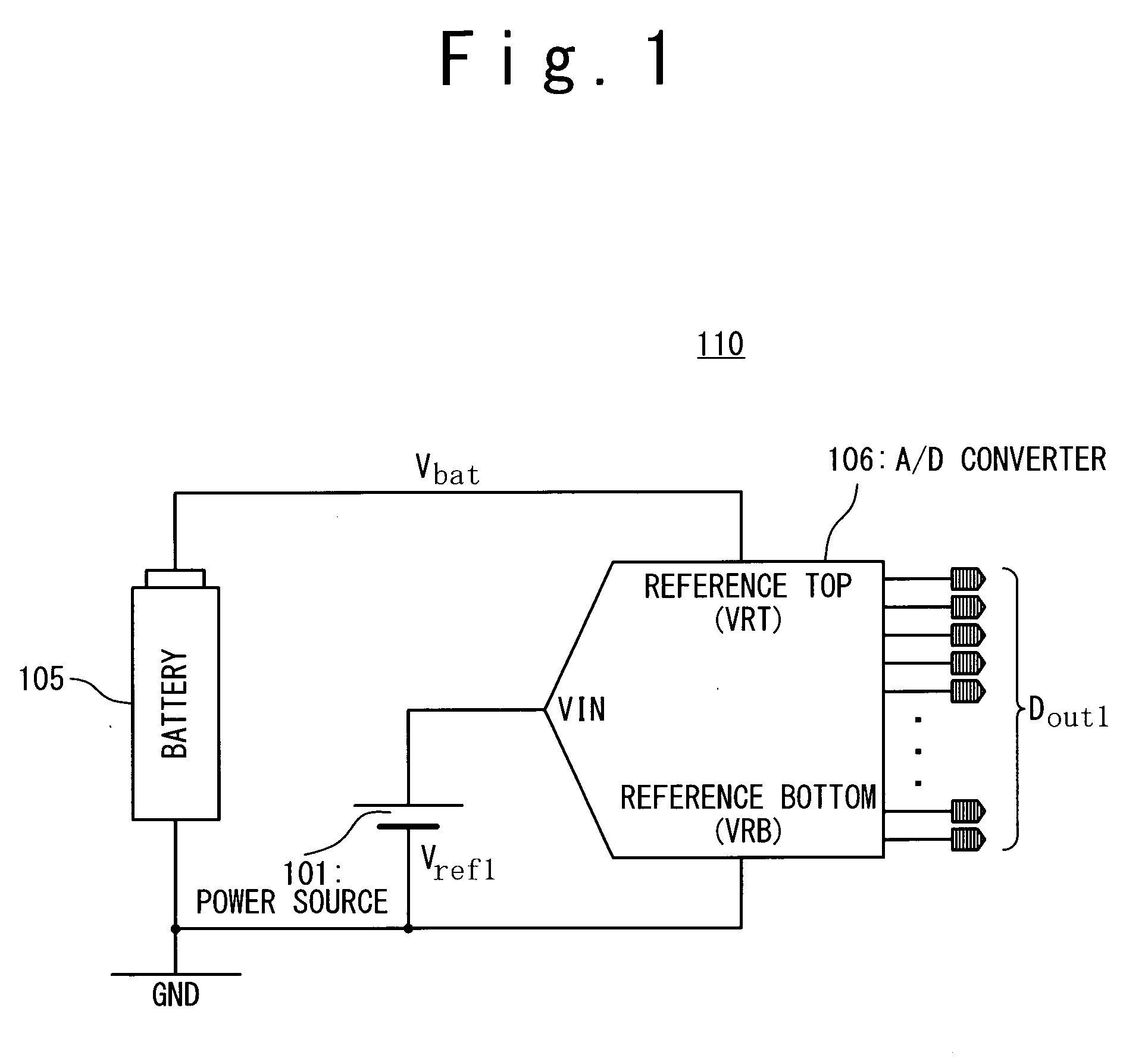
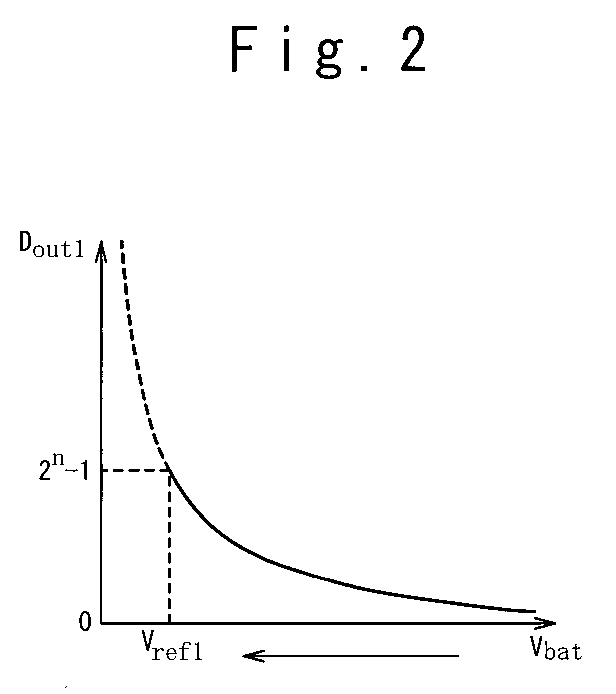
[0022]In the present invention, by setting a value of the voltage between the terminals to be a small value, the battery voltage near the discharge end voltage can be measured with high accuracy.

Problems solved by technology

In this case, scale of circuit becomes large, resulting in an increase in power consumption.

Method used


Image

  • Battery voltage measuring system
  • Battery voltage measuring system
  • Battery voltage measuring system

Examples


Embodiment Construction

[0041]Hereinafter, a battery voltage measuring system according to embodiments of the present invention will be described in detail with reference to the attached figures.

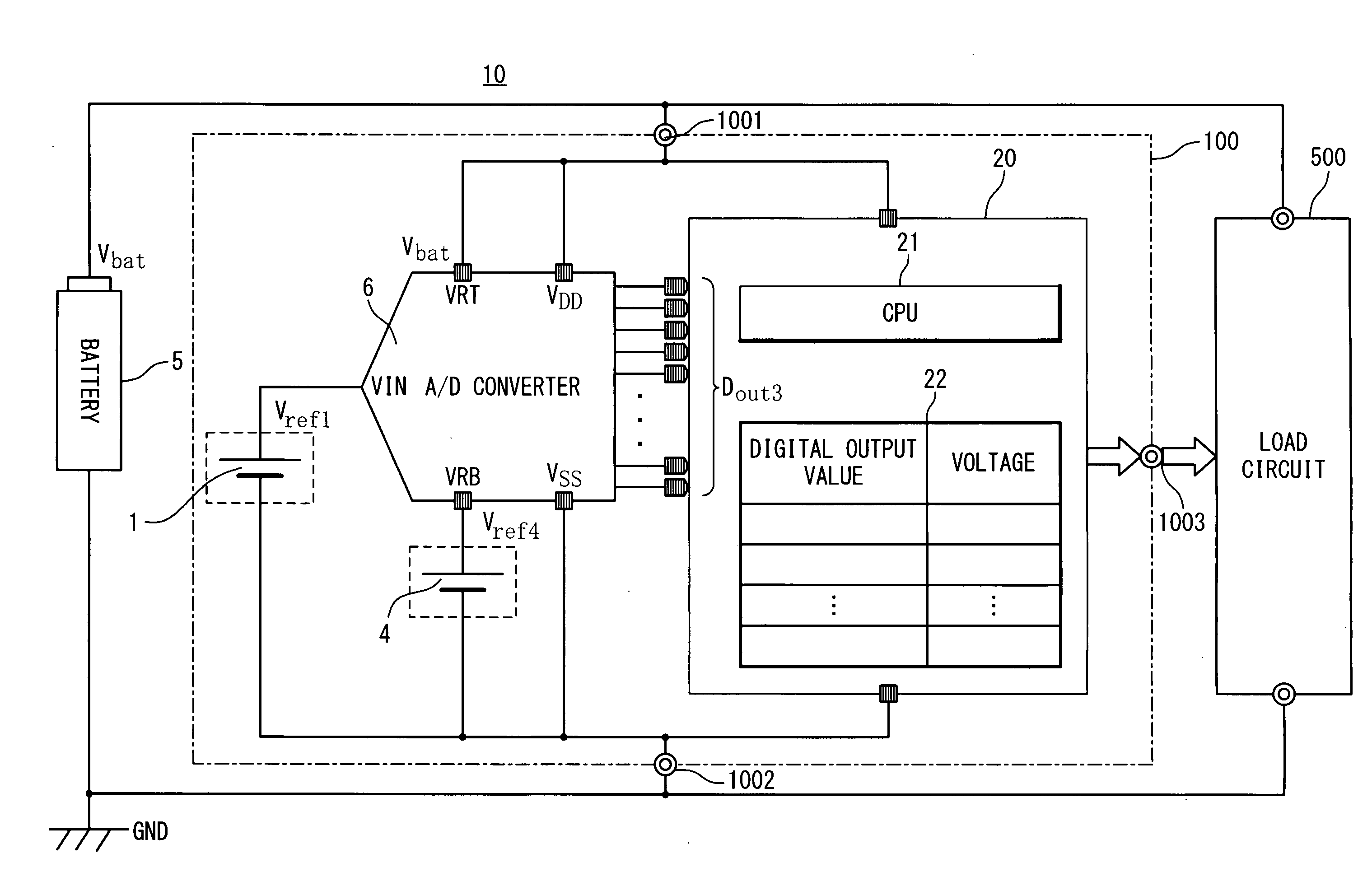
[0042]FIG. 5 shows a configuration of the battery voltage measuring system 10 according to the embodiments of the present invention. The battery voltage measuring system 10 is composed of a battery 5, and a battery voltage measuring circuit 100. The battery 5 is connected to a load circuit 500. The battery voltage measuring circuit 100 is realized as an integrated circuit (IC) in this example but may be realized by individual circuits. The battery voltage measuring circuit 100 has reference voltage sources 1 and 4, an analog / digital (A / D) converter 6 and a control unit 20.

[0043]The battery voltage measuring circuit 100 according to a first embodiment of the present invention is separated from a mobile device in which the battery 5 is installed. The battery voltage measuring circuit 100 according to a second embodim...


PUM


Abstract

A battery voltage measuring system includes an analog / digital converter configured to receive a higher reference voltage and a lower reference voltage which is lower than the higher reference voltage and to outputs a digital output value based on an input voltage which is lower than the high voltage reference voltage and is higher than the low voltage reference voltage. A battery supplies a battery voltage as the higher reference voltage to the analog / digital converter; a first power supply supplies a first reference voltage as the input voltage to the analog / digital converter; and a second power supply supplies a second reference voltage as the lower reference voltage to the analog / digital converter.

Description

BACKGROUND OF THE INVENTION[0001]1. Field of the Invention[0002]The present invention relates to a battery voltage measuring system for measuring voltage of a battery mounted in a portable device. This Patent Application is based on Japanese Patent Application No. 2007-004274. The disclosure of the Japanese Patent Application is incorporated herein by reference.[0003]2. Description of Related Art[0004]Portable devices driven by cells or batteries have been known. The portable devices are such as a notebook-sized PC (Personal Computer), a mobile phone, a PDA (Personal Digital Assistant), a digital camera, a digital video (digital video camera) and a portable audio device. In recent years, capabilities of the portable devices have been dramatically improved by accompanying downsizing and advancement of semiconductor devices built therein. In conjunction with this, a control of voltage of the battery built in the portable device (battery voltage) has become important to operate the por...

Claims


Application Information

Patent Timeline
IPC IPC(8): G01R31/36
CPCG01R31/3648G01R19/16542
Inventor NISHIMOTO, MASASHI
Owner RENESAS ELECTRONICS CORP
Learn More