
Signal light using phosphor coated leds

a technology of leds and signal lights, applied in the field of light sources, can solve the problems of increasing material costs, increasing energy costs, and poor energy efficiency of yellow led lights, and achieve the effect of improving efficiency and improving efficiency

Active Publication Date: 2008-07-17
DIALIGHT CORP
View PDF29 Cites 8 Cited by
  • Summary
  • Abstract
  • Description
  • Claims
  • Application Information

AI Technical Summary

Benefits of technology

[0008]In one embodiment, the present invention provides a method for creating an improved traffic signal light. The improved traffic signal light may utilize LEDs of improved efficiency at high temperatures. The LEDs of improved efficiency may be used alone or may be combined with one or more other types of LEDs. For example, the signal light comprises a housing, at least one outer lens and at leas

Problems solved by technology

Previous yellow LED lights generally exhibit relatively poor energy efficiencies due to high degradation in light output at extreme temperatures, high or low.
Consequently, poor energy efficiencies may increase material costs, energy costs, and reduces the signal light life due to internal heating of electronic components.
Reduced efficiencies may also limit the light intensity of the signal and create safety risks.

Method used


Image

  • Signal light using phosphor coated leds
  • Signal light using phosphor coated leds
  • Signal light using phosphor coated leds

Examples


Embodiment Construction

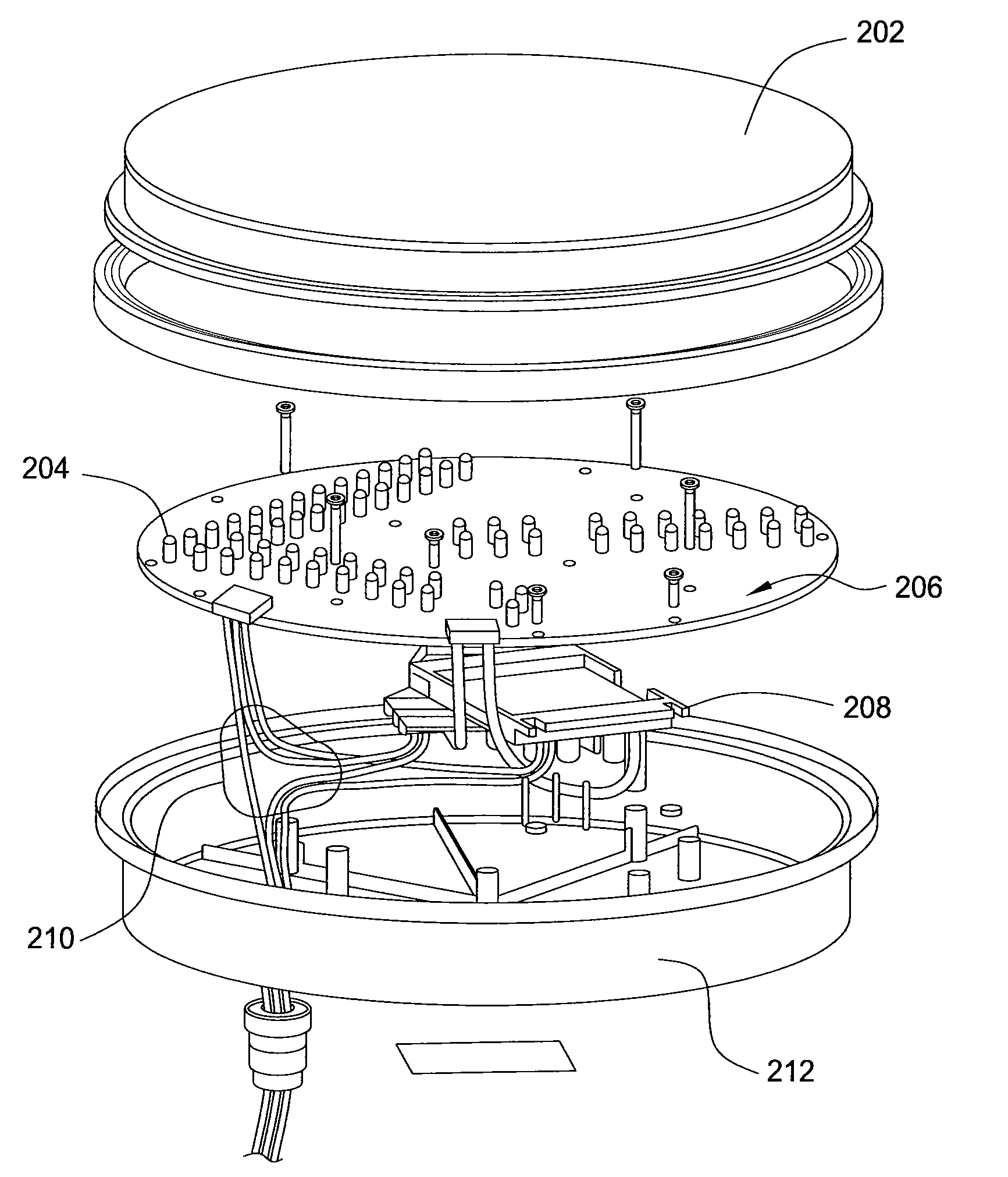
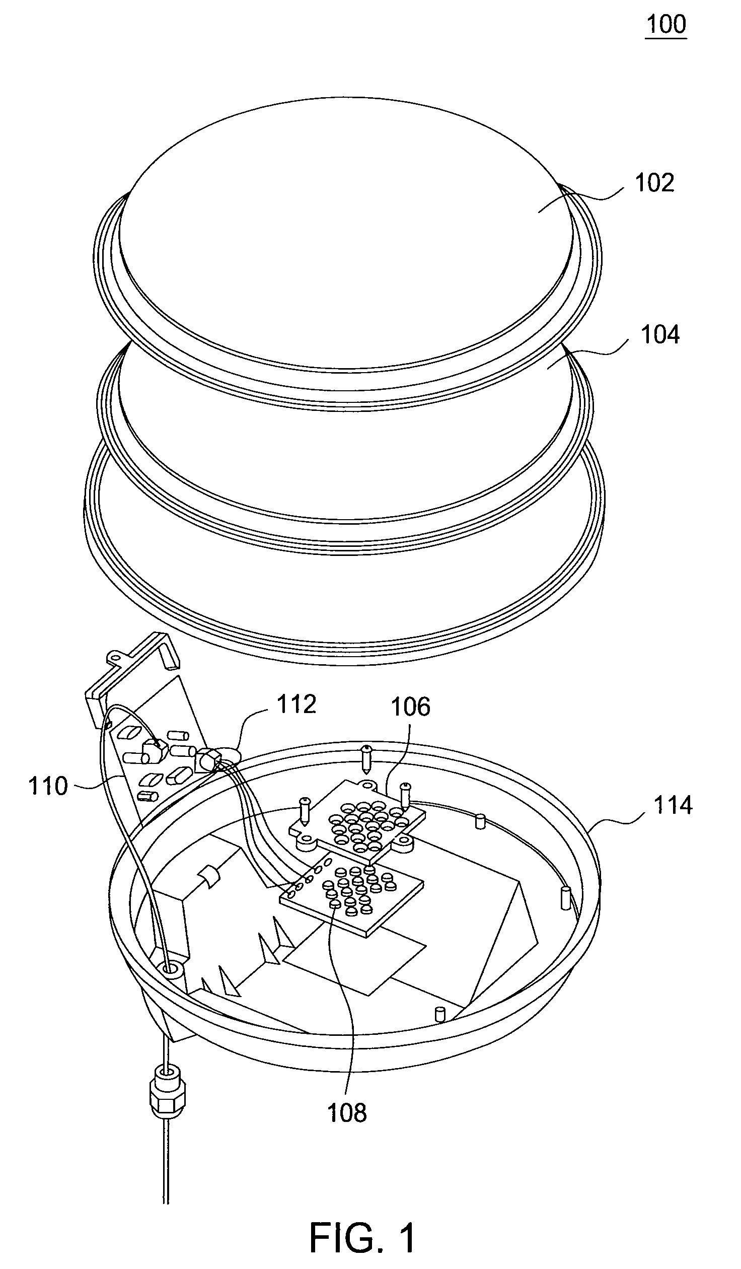
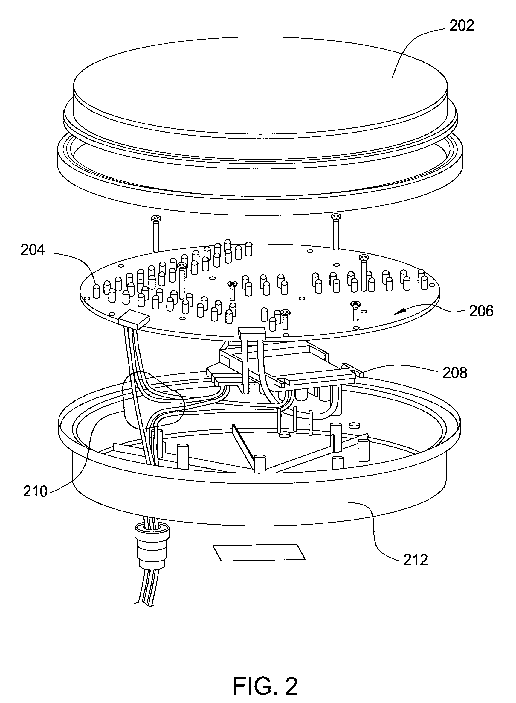
[0022]FIG. 1 illustrates an exploded view of an exemplary traffic signal light 100 according to one embodiment of the present invention. Traffic signal light 100 may comprise an outer lens 102, a mixing lens 104 such as, a Fresnel lens for example, and an array of light emitting diodes (LED)108. In the exemplary embodiment depicted in FIG. 1, LEDs 108 may be high powered LEDs such as, for example, Hi-Flux LEDs. LEDs 108 may also be 5 millimeter (mm) discrete LEDs, as depicted in FIG. 2 and discussed below.

[0023]The outer lens 102 may be smooth or may have a scattered surface depending on if the outer lens 102 simultaneously serves as a filter (not shown) and / or serves as the mixing lens 104, as discussed below. The outer lens 102 may also comprise optical features to help diffract light into a desired angular direction.

[0024]LEDs 108 may be placed in a reflector 106. Reflector 106 may comprise individual reflector cups for each one of the LEDs 108. LEDs 108 may comprise one or more ...


PUM

PropertyMeasurementUnit
Fractionaaaaaaaaaa
Nanoscale particle sizeaaaaaaaaaa

Abstract

An improved signal light and method for making an improved signal light is disclosed. For example, the improved signal light includes a housing, at least one outer lens and at least one or more second type of light emitting diodes (LEDs) deployed in the housing. The at least one or more second type of LEDs includes a pump, a phosphor and a filter having a cutoff point less than or equal to 540 nanometers (nm). The at least one or more second type of LEDs also has a pump peak wavelength less than or equal to 430 nm and has a phosphor with a peak wavelength greater than 575 nm.

Description

RELATED APPLICATIONS[0001]This application is a continuation-in-part of co-pending U.S. patent application Ser. No. 11 / 618,512, filed on Dec. 29, 2006, entitled METHOD AND APPARATUS FOR PROVIDING A LIGHT SOURCE THAT COMPINES DIFFERENT COLOR LEDS, which claims priority under 35 U.S.C. § 119 (e) to U.S. provisional patent application Ser. No. 60 / 755,704, filed on Dec. 30, 2005, which is hereby incorporated by reference in its entirety.BACKGROUND OF THE INVENTION[0002]1. Field of the Invention[0003]The present invention generally relates to a light source, and more particularly to a light-emitting diode (LED) based signal lights. The present invention provides for a method of creating a more efficient signal light.[0004]2. Description of the Related Art[0005]Signal lights, such as yellow traffic lights or rail signals for example, provide visual indications. Previous yellow LED lights generally exhibit relatively poor energy efficiencies due to high degradation in light output at extre...

Claims


Application Information

Patent Timeline
IPC IPC(8): F21V5/00
CPCF21K9/00Y10T29/49002F21Y2101/02F21W2111/02F21Y2115/10F21V5/00G08G1/095
Inventor CURRAN, JOHNPECK, JOHN PATRICK
Owner DIALIGHT CORP
Learn More