
Medical Handle

Active Publication Date: 2008-07-17
ARTHREX
View PDF19 Cites 30 Cited by
  • Summary
  • Abstract
  • Description
  • Claims
  • Application Information

AI Technical Summary

Benefits of technology

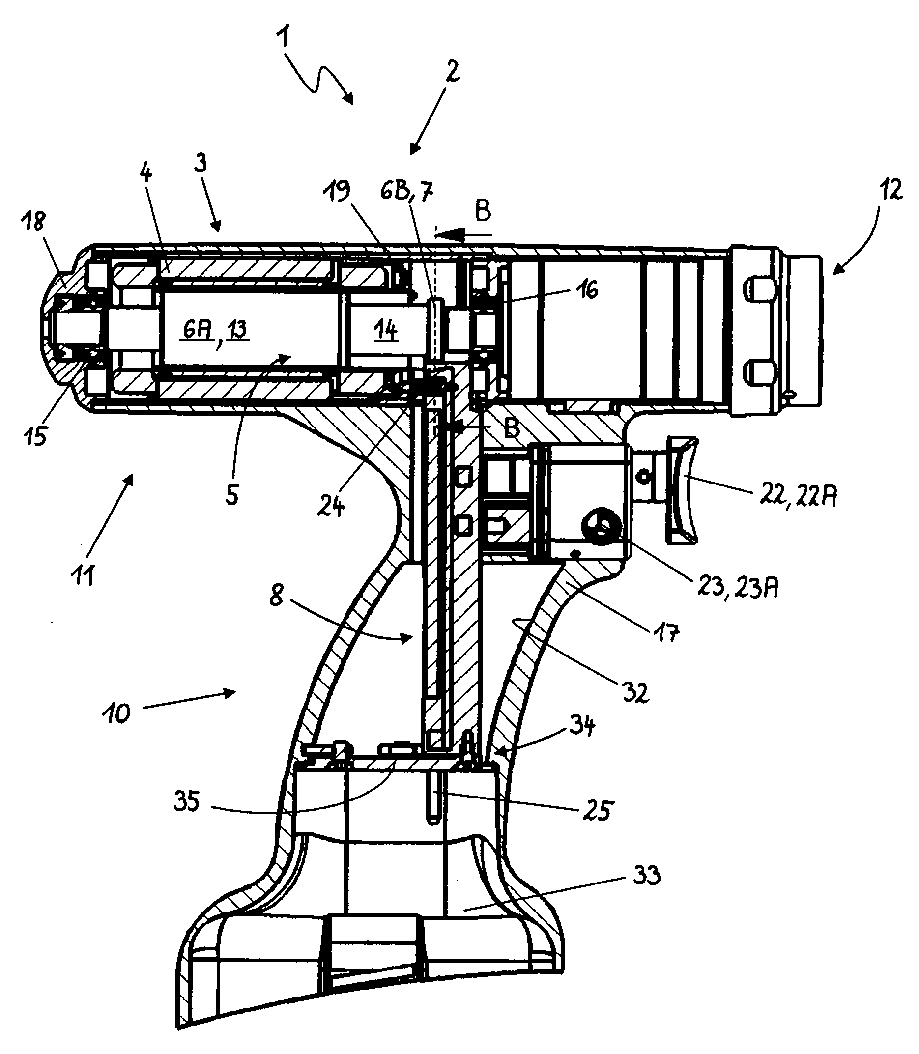
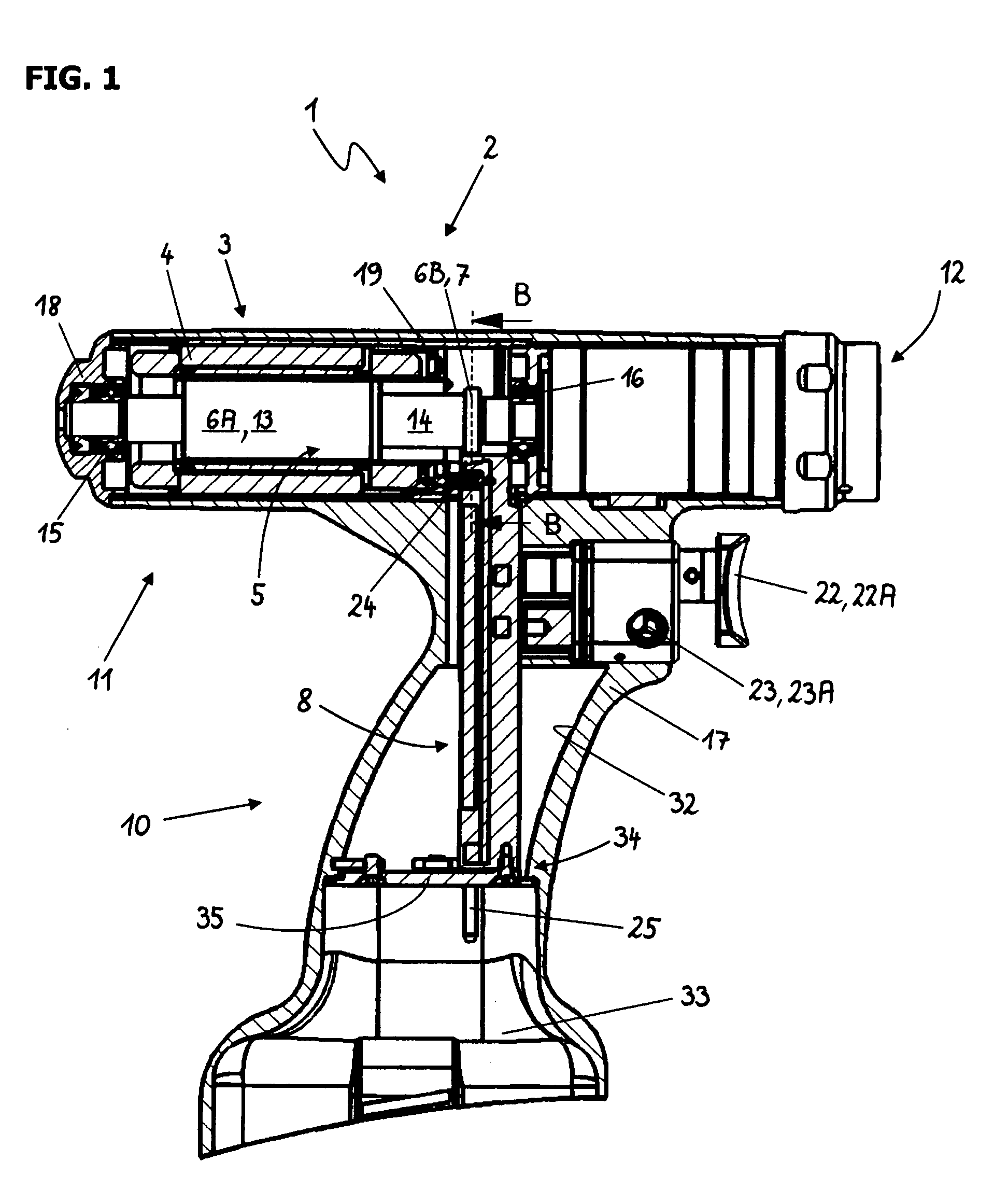
[0011]According to one embodiment of the medical handle the sensor system for detecting or determining the alignment, i.e., the angle of rotation, of the at least one magnetic element (motor sensor system) and the control and / or regulating circuit are combined in a common control module. Combining the motor sensor system and the control and / or regulating circuit into a one-piece component simplifies assembly and greatly facilitates installation in the handle in particular. To allow these parts to be combined into a one-piece control module and be used in the medical handle, it is also necessary to modify the design of the handle and to arrange the sensor system, the control and / or regulating circuit and, optionally, additional components installed in the control module, accordingly. Additional components installed in the control module may include in particular at least parts of the circuit for selecting the drive rotational speed and / or at least parts of the circuit for selecting the direction of rotation of the brushless electric motor and / or electric contacts to an energy source and / or contacts for connecting the control module, in particular the control and / or regulating circuit, to the drive unit and / or at least parts of a circuit for temperature monitoring of heat-emitting components of the handle, e.g., batteries and / or at least parts of a circuit for voltage monitoring of voltage-carrying components of the handle, e.g., for low-voltage shutdown of batteries.
[0013]In a first embodiment, the medical handle is equipped with a grip section and a function section arranged at an angle thereto, comprising, for example, the tool receptacle, an illumination device, media lines and other function elements, wherein the at least one magnetic element is arranged in one of the two sections and the control module is accommodated at least partially in the section in which the at least one magnetic element is not situated. The brushless motor is preferably also accommodated in the function section, wherein the at least one magnetic element is arranged in an area of the function section, where the grip section is connected so that the control module is accommodated at least partially in the grip section. One advantage of this embodiment is that at least parts of circuits that cooperate with control members that may be arranged on or attached to the grip section may be integrated into the control module in such a way that preferably all circuits are combined in a single compact control module. These additional circuits may be, for example, a circuit for selecting the drive rotational speed or a circuit for selecting the direction of rotation of the brushless electric motor. Another advantage of this embodiment is the excellent utilization of the available space in the interior of the handle, in particular when the control module has an elongated narrow preferably essentially square shape, so that it can be installed with no problem in the grip section of the handle.
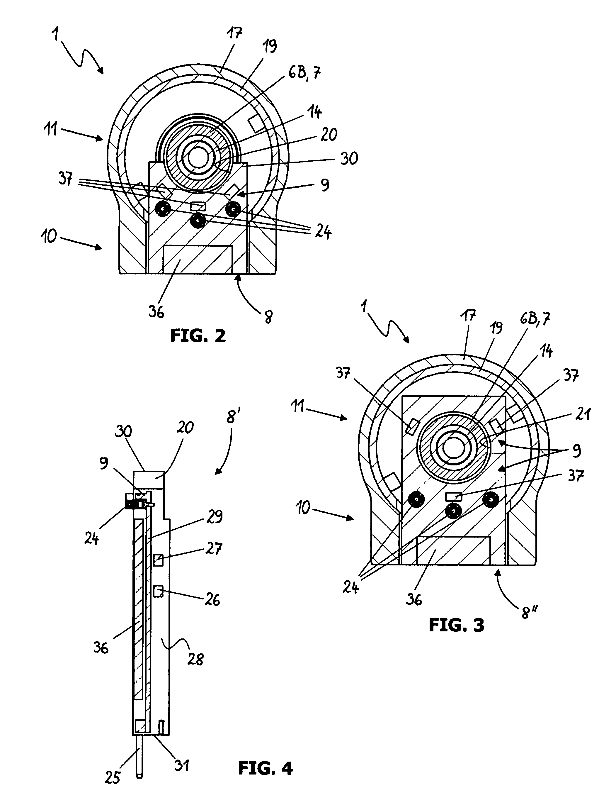
[0016]In one additional embodiment, to further improve on the determination of the alignment of the at least one magnetic element by the sensor system, the control module is provided with a defined exterior shape, so that the arrangement of the control module in the immediate vicinity to be at least one magnet is additionally facilitated and promoted. In particular the control module comprises an accommodation for at least partially accommodating or surrounding the at least one magnetic element. The control module preferably has a setback in the form of an arc of a circle or a step or it has a bore for at least partially accommodating the at least one magnetic element. The sensor system is especially preferably mounted immediately adjacent to the setback or the bore.
[0017]To facilitate handling and to simplify installation in the handle, the control module preferably has a carrier device, in particular a carrier plate or a circuit board to which at least the control and / or regulating circuit and the sensor system are attached, especially preferably also at least parts of other circuits.
[0020]Another advantage of combining the sensor system and the control and / or regulating circuit in a joint control module consists of simple alignment of the sensor system with the at least one magnetic element, e.g., a sensor magnet. The exact alignment of the sensor system is extremely important for the operating performance of the drive unit, in particular for the precise control and power supply to the brushless electric motor. The precise arrangement of the sensor system with respect to the at least one magnetic element is achieved by a precise defined distance of the sensor system from at least one other component provided in the control module. Contacts which connect the control module to other components in the handle and / or by means of which the control module can be connected to other components are preferably used for this, especially preferably the contacts that connect the control module to the drive unit. These contacts may be designed as plug contacts, for example, so that by installing the control module in the handle, in particular by plugging the contacts together, not only the connection of the control module to the drive unit is accomplished, but at the same time the arrangement and accurate alignment of the sensor system with respect to the at least one magnetic element are also achieved.

Problems solved by technology

The disadvantage of such an embodiment lies in its complex design, which necessitates several steps during assembly, in particular mounting the sensor system on the stator, installing the control device in the handle and connecting the sensor system to the control device via multiple lines.
The points of admission of lines and cables into the cast material or the housing constitute weaknesses where leakage may occur and subsequently water vapor or corrosive media such as cleaning agents can penetrate to the electric and electronic components and damage them, resulting in premature failure of the handle and necessitating complex repair measures or complete replacement of the device, which is a disadvantage.
Finally, there is repeatedly the problem that while connecting the sensor system to the electric motor by casting with resin the insulation of the signal line between the sensor system and the control device may melt, so that satisfactory functioning of the handle is impaired.

Method used


Image

  • Medical Handle
  • Medical Handle
  • Medical Handle

Examples


Embodiment Construction

[0026]The handle 1 shown in FIG. 1 is designed as a pistol shaped instrument comprising one or more outer sleeves 17, a function section 11 and a grip section 10 arranged at an angle to the former. However, the present invention is not limited to this shape of the handle but instead it may also be applied equally to other types of handles. The drive unit 2, comprising at least one brushless electric motor 3 with a stator 4 and a rotor unit 5, and the tool receptacle or a connection device 12 for connecting the handle 1 to a tool receptacle are both accommodated in the function section 11. A sealing cap 18, which seals the function section 11 and accommodates or supports on shoulders and setbacks components arranged in the interior of the handle 1, is provided on the end of the tubular or sleeve-shaped function section 11, which is opposite the end with the tool receptacle or the connecting device 12.

[0027]In a known way, both the drive unit 2 and the function section 11 may also con...


PUM


Abstract

A medical handle comprises a drive unit and a control device or circuit for driving a medical tool. The control device or circuit comprises a control and / or regulating circuit for controlling and / or regulating the drive unit, the drive unit comprises at least one magnetic element and a sensor system for determining the alignment of the at least one magnetic element. To achieve simpler assembly and a greater resistance to the ambient conditions that prevail during sterilization in comparison with known handles, the sensor system and the control and / or regulating circuit are combined in a joint control module, and the at least one magnetic element is arranged in the medical handle in such a way that at least a part of the control module can be positioned in the immediate vicinity of the at least one magnetic element and that the sensor system is arranged in the control module in such a way that it can be positioned in the immediate vicinity of the at least one magnetic element.

Description

CROSS REFERENCE TO RELATED APPLICATION[0001]The present application claims priority from pending European Patent Application No. 07000834.7, filed Jan. 17, 2007, which is incorporated herein by reference.BACKGROUND[0002]1. Field[0003]The present application relates to a medical handle having a drive unit for driving a medical tool and a control and / or regulating circuit for controlling and / or regulating the drive unit.[0004]2. Description of Prior Art[0005]Such handles are widely used today for a number of different medical, surgical and cosmetic procedures. The drive unit of these handles often comprises a brushless electric motor which generates a rotational movement that is transferred to a treatment tool. The drive unit may optionally have one or more shafts for transferring the rotational movement, gears or devices for converting the rotational movement into a different type of motion.[0006]Brushless electric motors for the handles are usually controllable and in most cases the...

Claims


Application Information

Patent Timeline
IPC IPC(8): H02P5/00
CPCA61B17/32002A61B2017/320028H02K29/08H02K7/145H02K11/0021A61B2019/4868H02K11/215A61B2090/0813
Inventor SCHNEIDER, RAINERSCHROECK, RAINERPLETSCHER, WALTEROTT, JOSEF
Owner ARTHREX
Learn More